Radial Inflow Equation
Although it is clear from the foregoing that if the inflow can be determined, considerable information about the rotor performance can be obtained. The issue is now to devise an approach that can solve for the inflow directly, without making any assumptions as to its magnitude or form. One solution can be obtained using a hybrid blade element and momentum approach using the principles of the equivalence between the circulation theory of lift the momentum theory of lift. From the BET it has been shown in Eq. 3.15 that the incremental thrust produced on an annulus of the disk is
dCT = vQr2 dr = ^y^ {Or2 – kr) dr. (3.57)
Equating the incremental thrust coefficients from the momentum and blade element theories (using Eqs. 3.45 and 3.57) we find that
^y^ (6r2 – kr) =4k(k- kc) r, (3.58)
which gives
а С, о Cl о
—~^0r——— —k = k2- kck (3.59)
or
This quadratic equation in k has the solution
![]()
A(r, kc) =
|
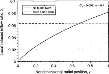
Figure 3.5 Distribution of inflow for an ideally twisted blade as predicted by the BEMT compared to an untwisted blade. |
Equation 3.62 allows for a solution of the inflow as a function of radius for any given blade pitch, blade twist distribution, planform (chord distribution), and airfoil section (through the effect of lift-curve-slope Cia and zero-lift angle «о via в). When the inflow is obtained, the rotor thrust and induced power may then be found by integration across the rotor disk usinv Eos. 3.48 and 3.49.
—- G7 – A – – – – – — _ – – _ .
For an untwisted blade of constant chord and uniform airfoil section, the distribution of inflow as predicted by Eq. 3.62 is shown in Fig. 3.5, and is compared with the uniform inflow at the same thrust coefficient. For the untwisted blade the distribution of inflow is concentrated toward its tips (i. e., n — 1 in Eq. 3.50). Clearly, the combination of blade geometric parameters for the results shown in Fig. 3.5 is nonideal because as shown by Eq. 3.56 the induced power will be higher than the minimum possible with uniform inflow (n = 0). We must now proceed to examine how the blade geometric properties could be adjusted to give a more uniform inflow and, therefore, to minimize the induced power requirements for the rotor.


