Static Stability and Control
3.1 Maneuverability—Elevator Angle per g
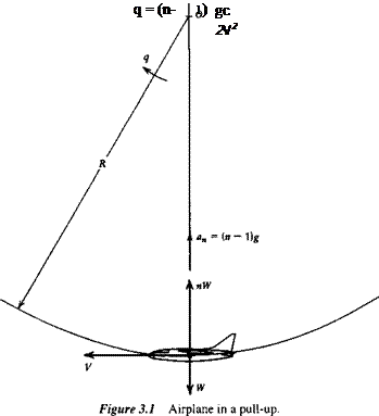
In this and the following sections, we investigate the elevator angle and control force required to hold the airplane in a steady pull-up with load factor1 n (Fig. 3.1). The concepts discussed here were introduced by S. B. Gates (1942). The flight-path tangent is horizontal at the point under analysis, and hence the net normal force is L — W = (n — 1)W vertically upward. The normal acceleration is therefore (n — 1 )g.
When the airplane is in straight horizontal flight at the same speed and altitude, the elevator angle and control force to trim are 8e and P, respectively. When in the pull-up, these are changed to 8e + A8e and P + ДP. The ratios Д8J(n – 1) and AP/(n — 1) are known, respectively, as the elevator angle per g, and the control force per g. These two quantities provide a measure of the maneuverability of the airplane; the smaller they are, the more maneuverable it is.
The angular velocity of the airplane is fixed by the speed and normal acceleration (Fig. 3.1).
![]() (n ~ l)g
(n ~ l)g
V
As a consequence of this angular velocity, the field of the relative air flow past the airplane is curved. It is as though the aircraft were attached to the end of a whirling arm pivoted at О (Fig. 3.1). This curvature of the flow field alters the pressure distribution and the aerodynamic forces from their values in translational flight. The change is large enough that it must be taken into account in the equations describing the motion.
We assume that q and the increments Да, A8e etc. between the rectilinear and curved flight conditions are small, so that the increments in lift and moment may be written
Д CL = CLa Да + CLqq + CLsA8e (3.1,2)
ДСт = CmAa + Cmqq + CmsA8e (3.1,3)
where, in order to maintain a nondimensional form of equations, we have introduced the dimensionless pitch rate q = qc/2V, and CLq = dCJdq, Cmq = dCJdq. The q de-
‘The load factor is the ratio of lift to weight, n = LAV. It is unity in straight horizontal flight.
 |
rivatives are discussed in Sec. 5.4. In this form, these equations apply to any configuration. From (3.1,1) we get
which is more conveniently expressed in terms of the weight coefficient Cw and the mass ratio /jl (see Sec. 3.15), that is,
q = in – 1) —’- (3.1,4)
2/x
Since the curved flight condition is also assumed to be steady, that is, without angular acceleration, then ACm = 0. Finally, we can relate AC, to n thus:
![]() nW-W
nW-W
ACl = pVzs ={n~ 1)Cw Equations (3.1,2 and 3) therefore become
which are readily solved for Да and Д8e to yield the elevator angle per g
and
where det is the same expression previously given in (2.4,13d). As has been shown in Sec. 2.4 det does not depend on CG position, hence the variation of Д8J(n — 1) with h is provided by the terms in the numerator. Writing Cma = CL(h — hn) (3.1,6a) becomes
![]() A8e CWCL (2fx – CL) ( Cm
A8e CWCL (2fx – CL) ( Cm
—- «_ =—— w L«y P— V h_h + ———- Hi—
n — 1 2 fidet 2/i — CLq
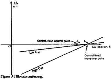
The derivatives CLq and Cm both in general vary with h, the former linearly, the latter quadratically, (see Sec. 5.4). Thus (3.1,7), although it appears to be linear in h, is not exactly so. For airplanes with tails, CLq can usually be neglected altogether when compared with 2fi, and the variation of Cmq with h is slight. The equation is then very nearly linear with h, as illustrated in Fig. 3.2. For tailless airplanes, the variation may show more curvature. The point where Д8J(n — 1) is zero is called the control-fixed maneuver point, and is denoted by hm, as shown. From (3.1,7) we see that
where Cmq(hm) and CLq(hm) are the values of these two derivatives evaluated for h = hm. When Cmq and CLq can be assumed to be independent of h, (3.1,7) reduces to
 |
The difference (hm — h) is known as the control-fixed maneuver margin.


