Tandem Rotor Systems
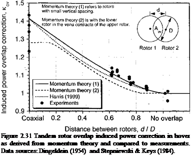
The basic momentum analysis can also be extended to overlapping tandem rotors. Tandem rotor designs are sometimes used for heavy-lift helicopters because like the coaxial design all of the rotor power can be used to provide useful lift. However, like a coaxial design, the induced power of partly overlapping tandem rotors is found to be higher than that of the two isolated rotors (Fig. 2.31). This is because one of the rotors must operate in the slipstream of the other rotor, resulting in a higher induced power for the same thrust. The tandem rotor problem is discussed extensively by Stepniewski (1955) and Stepniewski & Keys (1984). Other results for twin rotor performance are given by Fail & Squire (1947) and Sweet (1960).
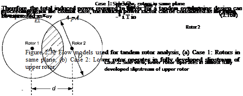
The analysis of overlapping rotors from the perspective of momentum theory is normally based on the ideas of overlapping areas – see Payne (1959). Let Aov = mA be the overlap area according to the inset shown in Fig. 2.31 and also Fig. 2.32. The rotors are assumed to have no vertical spacing, which is Case 1 shown in Fig. 2.32. By means of the geometry of the problem it can be shown that
![]()
 |
m’ = = — Г# — — sinfll, where в = cos 1 (—^ .
А ті D dJ
 |
Let T and T2 be the thrusts on the two rotors, which may be unequal. Therefore, m(T + T2) is the thrust on the overlapped region. Based on uniform inflow assumptions then the induced power of the rotors consumed by each of the areas is
|
(1 – m’yrV1 + (1 – m’)7f2 + m'(T + T2f/2 |
 |
where A is the disk area of any one of the two rotors and T is the total system thrust as generated by both rotors. If it is assumed that each rotor carries an equal fraction of the total thrust (T[ — Tf) then
= kov = 1 + (V2 – l)m’ = 1 + 0.4142 m’, (2.169)
where m! is given by Eq. 2.164. Harris (1999) suggests an approximation to кт, where
The assumptions made in the derivation of the previous equations are not critical, as it can be shown that if each rotor carries a different fraction of the total thrust then /cov is only slightly higher than if an equal fraction is assumed (see Question 2.21). Notice that in Eq. 2.169 asm’ -> 1, which is a coaxial, then kow •v/2, as before. When the rotors are completely separated with no overlap (m’ = 0), then kow —> 1, as is required for isolated
rotor performance. The result of Eq. 2.169 is plotted in Fig. 2.31 in terms of the spacing ratio d/D, where d is the spacing between the two rotor axes and D is the rotor diameter. As d becomes larger and the rotors are more separated, the induced power overlap correction factor approaches unity.
An alternative analysis is to consider a situation where the lower rotor of the tandem operates in the fully contracted slipstream of the upper rotor – see Case 2 of Fig. 2.32. Here the overlap area is affected by the contracting wake from the upper rotor and m’ must be determined by numerical integration. When the rotors are in the same plane then m’ is given by Eq. 2.164. The analysis proceeds using as similar flow model to that shown previously in Fig. 2.27. Using the conservation of momentum, the thrust on the upper and lower rotors are
 Tu = (p Avu)(2vu)
and
Ti = (mw)i – (mw)u.
The mass flow rates through the two rotors are
mu = m p A(2vu) and mi = (1 — m’)p Avi + m p A(i>/ + 2vu).
Assuming the thrust on the upper and lower rotor are equal gives
[(1 – m’)p Avi + m’p A(vi + 2vu)]wi – [m’p A(2uM)](2u„) = (p Avu)(2vu),
(2.174)
which after simplification becomes
![]()
![]() vl(4m’ + 2)
vl(4m’ + 2)
Щ
From the conservation of energy
Pi = T[(l – m’)vi + mvi + 2vu)] = Qmw2^ – Qraw2^ , (2.176)
which can be simplified to get

 |
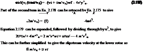
T(vi + 2m vu) = A(vi + 2m’vu)wf – 4p m’Av3u. Equation 2.171
The dependency of кт on rotor overlap has been measured experimentally using subscale rotor models. The amount of these data is relatively scarce compared to single rotor data, but the available results have been collated by Stepniewski & Keys (1984) from several sources including Sweet (1960) and Boeing-Vertol experiments. Their results showing the relationship between /cov and the overlap d/D have been reproduced in Fig. 2.31. It is apparent that the momentum theory result gives good agreement with the measurements, although the approximate result given by Harris (1999) underpredicts /cov. For tandem rotor designs, such as the CH-46 and CH-47 models, d/D is approximately 0.65, giving /cov of about 1.13. Unfortunately, because the interference effects are related to the vertical spacing between the rotors as well as the degree of overlap, the results shown in Fig. 2.31 indicate some variance. Also, Dingeldein (1954) shows results that suggest /cov to be less than unity urtian fba гглілгс огд mef oanorofA/^ cuoli fhof // / П
VV liVli U1V IV/IVIO CUV JUOl OV^/Ul UCVU OUV11 C11UC u I IS exists – see data in Fig. 2.31. Apart from this anomaly, the correlation of Eq. 2.169 or Eq. 2.187 with the measured data is sufficiently good to enable the momentum theory to be used for at least the preliminary estimation of tandem and coaxial rotor performance.
In forward flight, both coaxials and tandem rotors systems appear to behave very much like two single rotors but with one or the other of the rotors operating in the fully developed downwash of the other rotor – see Dingeldein (1954). Stepniewski & Keys (1984) discuss induced power interference effects and tandem rotor performance in forward flight. See also the discussion in Section 5.5.11 for forward flight performance predictions of coaxial and tandem rotors.


