WINGS WITH END PLATES
End plates have found little application on airplane wings until recently when the winglet and/or tip sails have been applied to reduce the induced drag, the drag due to lift. As the induced drag of a wing is a large part of the total a device that can reduce this component is of importance. In considering such devices the improvement obtained must be weighed against that possible with an increase in the wing aspect ratio. With the available theoretical and experimental data the relative merits of wing and plates, winglets and similar devices can be found. The theoretical and experimental characteristics of the various types of end plates are presented as follows.
BASIC PRINCIPLES. The objective of adding wing end plates is to control the flow at the wing tip and to reduce the induced angle of attack and thus the induced drag. In some ways this is analogous to the operation of a wing between the walls in a wind tunnel and thus eliminating the three dimensional effects leading to the induced drag loss. Thus the addition of end plates would be in the limit a wing with the drag characteristics of a two dimensional section, an infinite aspect ratio wing. In any case when adding a pair of end plates, figure 14, the effective span is increased. Theory (17) considers a lifting line with an elliptical loading which is bent up at both ends. The results of this can be approximated in terms of an effective aspect ratio Ai = A – f aA, where
ДА/A ~ kh/b (16)
|
Figure 14 shows that this equation is confirmed, using к = 1.9, up to h/b = 0.4. Note that this type of effective A’ratio can be used both to calculate induced drag or the lift-curve slope. With the data given on figure 14 it does not matter whether the plates are attached nearer to the leading or trailing edge of the wing. Note that the effect of end plates is also obtained in swept wings (18,e) and essentially to the same degree as straight wings. 1 h POINTS AS IN I "FLUID-DYNAMIC DRAG"
|
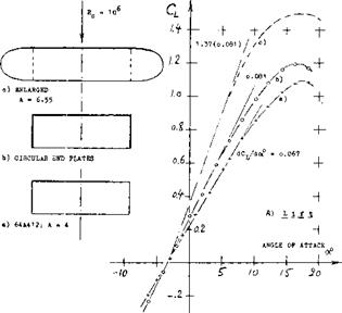 WINGS WITH AND WITHOUT END PLATES. The characteristics of wings with end plates and the wing with the plates used to extend the wing and so increase its aspect ratio is given on figure 15. As shown in figure 15,В DRAG, the drag of the wing with the end plates is less than the wing without them only above C^= .3. This is evidently a major reason for the fact that end plates are not usually applied in the design of airplanes. Aerodynamically, it is much more profitable to add end plates to the wing span thus gaining aspect ratio as well as lift-producing area. To demonstrate this point, we have analytically determined the CyCL) function for the enlarged wing as shown on figure 15. Based on the original area of the wing, we then find a reduction of the drag/lift ratio, for example at CL= 0.9, as against the original plane wing, twice as large as that obtained by means of the end plates. Below that lift coefficient, the wing with the enlarged span is clearly superior to the wing with end plates.
MAXIMUM LIFT. The end-plated wing in figure 15, shows an increase of the maximum lift coefficient from 1.1 to 1.2. The increment is 9%, while the enlargement of wetted area is almost 40%. Here again, a wing increased in span by adding the end-plate areas, is superior, resulting in a CLX= 1.38 (1.09) = 1.5. Of course, a larger span may be structurally undesirable. However, end plates at the wing tips are not desirable either. As a rule, therefore, end plates are used in the design of aircraft only under conditions where they may perform another function, in addition to improving the lift of the device to which they are attached. Such a case is for example a tailless airplane with a swept – back wing, where a pair of end plates serve in place of the vertical tail to provide directional stability and control. Another application of end plates can be found in hydrofoil boats, Chapter VIII where the span of a submerged wing may be limited to the dimension of the beam of the craft. End plates are also used in ground effect vehicles.
Although end plates do produce an increase in the effective aspect ratio which reduces the drag at very high lift coefficients only slight reductions in drag are obtained when operating at or near the cruise lift coefficients. At the cruise conditions the viscous and interference drag increments associated with the end plates are nearly as great as the reduction of the induced drag due to the effective increase in aspect ratio. While considerable testing has been done with wing end plates it is apparent from figure 15 that the optimum design had not been developed. If the wing span cannot be changed, the use of wing tip devices may be desirable. To develop an optimum wing tip configuration for this purpose it is necessary to examine the flow field in which the end plate must operate and then find the tip device required to give the desired performance.
|
Figure 15 Lift and drag of a rectangular wing (a) plain, as tested (18,b). (b) with circular end plates. (c) calculated with enlarged span. |
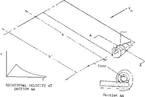
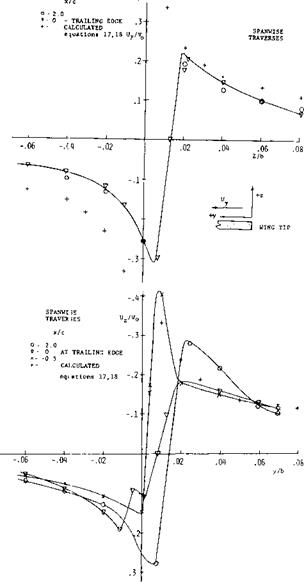
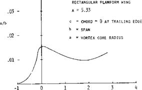
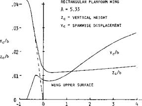
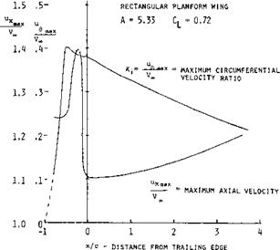
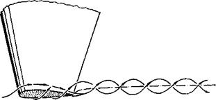
WING TIP FLOW FIELD. Detailed measurements of the velocity field at wing tips as influenced by the tip vortex have been made by a number of investigators, (16). Tests show that a main vortex forms over the wing surface as illustrated on figure 16. Between the main vortex and the wing tip a small secondary vortex is also formed as shown. At any station in the stream – wise direction the rotational velocity increases linearly with radius from the core center until the core diameter is reached. Then the velocity decreases as a direct function of the radius. Typical velocity distributions from (16,a) are given on figure 17 as a function of wing span station from the tip and the vertical distance showing these characteristics. The core radius reaches a maximum at the wing trailing edge and then decreases in size with downstream location until it again becomes larger starting at an axial distance of four wing spans downstream, figure 18. The location of the vortex core is inboard and above the wing tip as illustrated on figure 18. The variation of the axial velocity maxima and the circumferential velocity maxima as a function of the streamwise distance from the trailing edge is given on figure 20.
3-11
|
|
|
|
|
|
|
|
|
|
|
|
|
|
|
|
|
|
A comparison of the measured tangential velocity with that calculated using equations 17, 18 is given on figure 17. Here the velocity ratio at the wing trailing edge is very nearly the same as the value calculated at two chord lengths downstream where the vortices are rolled up. Although equations 17 and 18 were developed for the case where the vortices are completely rolled up it appears that to the first approximation they can be corrected using the data given on figure 20. fills is done by multiplying the calculated velocity ratio ot equations 17 and 18 by к equation 19.
к = u @ x/c = 2/ u @ x/c = x (19)
(16) character’-*.*’ t. r wng tip vortices:
a) C’higie-, v a. . – p Vortices Velocity AHS 27 Forum May ’71
b) Bet z,^ Be ha u. ot Vortex Systems, NACA TM 713, 1933
e) Donaldson. The Aircraft Vortex Problem ARAP No. 155 1971 A) Donaldson, Vortex Wake Conventional А/С, AGARD No. 204 e; Spreiter, et, і Ron лЧ up Trailing Vortex J. A. Sci. Jan. ’51 r irow, Effev. > ‘* C Qg on Tjp vortex j of А/С May 1968 Ю ^orsighs, H r v e wing Tip Surveys Jof А/С Dec. 1973 r.’*l! sow Ro1 eJ f p structure Vortices, J Of А/с Nov. 1973 О і tXormick, et al, Structure trailing vortices J А/С Jan. ’69
|
X/c DISTANCE FROM TRAILING EDGE Figure 18. Vortex core radius as function of downstream distance. |
(17) Available tneoretical results on end plates:
a) Ergebnisse AVA Gottingen Vol III (1927) p 18.
b) Mangier, Theoretical Analysis of End Plates, Lufo 1937 p 564 (NACA T Memo 856) and 1939 p 219.
c) Kiichemann, On Swept Wings, ARC CP 104 (1951).
d) Rotta, Plate at One End, Ing Archiv 1942 p 119.
e) Weber, Loads & Inboard Plates, ARC RM 2960 (1956).
|
x/c – DISTANCE FROM TRAILING EDGE Figure 19. Normal and spanwise displacement of vortex centerline. |
INDUCED DRAG RECOVERY. According to theory (16,b, c,d) all the swirl energy in the trailing vortex system is trapped within a distance from the centerline of the wing and for a considerable distance outboard. However, as indicated by theory and test the major portion of the rotational energy occures within a very small radius. This is confirmed by (16,c) where it was shown that 54% of the vorticity is within a radius up to
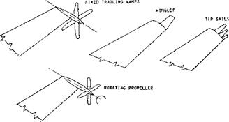
0. 1 of the wing span should be of sufficient size to obtain high energy recovery and a corresponding reduction of the induced drag. Devices that can be used to recover the energy of the tip vortex of a wing thus do not have to be large. Some of the devices that have been considered for this purpose are shown on figure 21 (18,n) and include winglets tip sails, fixed tip vanes and rotating propellers.
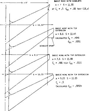
WINGLETS. Of the wing end plate devices considered the winglet appears to be the most effective for reducing the induced drag and effectively increasing the aspect ratio. Results of test data (18,k, l) show that using winglets the induced drag is decreased as much as 30% depending on the lift coefficient, figure 22. The winglets tested have the best performance at a wing lift coefficient of 0.5. It would be expected that a change in configuration could shift the C L for best recovery up or down.
The design and analysis of winglets is involved and complex due to the mutual interaction with the wing surface and the exact solution is not available (18,k). However, by assuming the tip vortex is only affected by the main wing the performance of winglets can be estimated by relatively simple methods. This is done by finding the local flow conditions at a series of winglet stations using equations 17 to 19 and the methods previously given. Knowing the flow conditions the force coefficients are found and resolved in the flight direction to find the change relative to the entire wing.
|
Figure 20. Variation of axial velocity maxima and circumferential velocity maxima as a function of streamwise distance. |
Consider a winglet mounted at the tip of a wing, figure 23, at any station r on the winglet the effective axial velocity, Vj^is influenced by the sweep of the leading edge and the angle of attack so
Vc= у cos (a + 0) (20)
where a = the main wing angle of attack
© = the angle of the winglet leading edge VL = the local axial velocity
The true velocity relative to the airfoil section W, is
W = v/+v* (21)
The rotational velocity v produced by the tip vortex is determined using equations 17 to 20. The apparent angle of attack at any wing tip station is, section AA, figure 23.
«.= A> + і (22)
where a. = apparent wing angle = tan v/V£ і = winglet section incidence
|
Figure 21. Wing tip vortex energy drag recovery devices. |


![]() ,5 OPERATION
,5 OPERATION
^—————- 1————— 1—————– 1—————– 1————— 1—————– 1________ I
0 .1 .2 .3 .4 .5 .6 .7
Figure 22. Comparison of induced drag ratio of wing with extended tip to that of a wing with winglets.
The lift and drag coefficients developed on the winglet can be found by assuming it is operating as a simispan wing due to the reflection plane characteristics of the main wing. Thus, knowing the effective aspect ratio of the winglet the lift angle and operating C^ can be found using equations 2 and 22. The drag coefficient is determined from standard data and the resultant force coefficient found from the equation
CR = CLvV/cos Y’ (23)
where Y – tan CDW / CLVv
As shown on section AA figure 23 the resultant force coefficient resolved in the direction of flight gives a change in the drag coefficient of the basic wing equal to
|
|
|
where S = area of the basic wing bV2 = the span of the winglet c’ = the chord of the winglet
Figure 23. Relation of winglet to basic wing with flow condition’ and force vectors. |
If the angle of the winglet relative to a line normal to the wing is the increase of lift on the basic wing is
ЛС, 2 ( CR cos(0 +Y’)sin0 WcW
TJn ———————— ^ (25)
Based on the above approach the drag reduction and the lift increase is in good agreement with the available test data.
|
Figure 24. Comparison of performance of wings with and without winglets. |
WINGLET PERFORMANCE AND APPLICA TION. Just as in the case of wings with end plates the application and performance advantages of winglets are dependent on the configuration of the wing, its aspect ratio and the total area. If the wing span is increased by the height of the winglet and the area held constant then as is shown in figure 24 the winglets have no performance advantage. Further if the wing span is increased with a corresponding increase in wing area the operating C L will decrease along with the induced drag and this along with the aspect ratio increase will give improved performance compared with the wing with winglets. Also if a wing tip extension is used that gives the same wing root bending moment as a wing with winglets there appears to be no performance advantage with the winglets. However, if a winglet is used on a wing there is a decrease in the induced drag of the order of 20% compared to the wing alone. Based on the above, figure 24 it appears that winglets are useful for increasing the performance of an existing wing but if a new wing configuration is to be designed the use of winglets will give little improvement.
Single End Plates, placed at only one end of a wing (17, d) have an effect which is roughly half of that of a pair of plates; id est, for small height ratios (up to h/b ==. 0.2), the maximum increase in effective aspect ratio is theoretically slightly less than
ДА/A == h/b (18)
A plate on one side has a definite limit, however, as to its effect. As the height ratio approaches infinity, the effective A’ratio is no more than doubled, while a pair of plates yields Aj_= oo. The function for a one-side plate plotted in figure 14 can be approximated by
А/ДА = (1 – (b/h)V»)*A (19)
Note that the ratios are reversed in this equation. As a practical example of “single” end plates, avertical tail surface is shown in “Fluid-Dynamic Drag” with a horizontal surface placed on top (serving as end plate). A;/A — 1.5, is thus obtained for the fin.
Wing-Tip Tanks (detachable or disposable) have become standard equipment in certain types of military airplanes (to extend their range). They are not really end plates. There is an end-plate effect involved, however. Three specific effects of tip tanks can be stated:
(a) Tip tanks usually extend beyond the lateral edge; they may thus increase area and aspect ratio.
(b) They can be expected to permit the flow, laterally to get around them, to a certain degree.
(a) Because of their height (equal to their diameter) and/or regarding their displacement, tip-mounted tanks have an effect similar to end plates.
A number of wind-tunnel tests is available (20) presenting the lift of wings or wing-body combinations, including a pair of tip tanks. Analyses as in (21) do not take into account the rolling-up of the wing-tip vortices. We will assume that the flow gets around each tank as far as qualitatively shown in figure 19, so that the span is effectively reduced at each wing tip, as against that between the outer sides of the tanks by Ab = — r, where r maximum radius of the tanks. Thus, for the two tanks Ab = — d, and ДА =■ — d/c. Definition of the effective wing area with and without the tanks is problematic. Using lifting-line principles, exact knowledge [38] is not necessary, however. Assuming the height of the “plates” representing the tanks, to be h = d, equation (25) indicates ДА/A = 1.9(d/b). Depending upon the manner in which the tanks are attached (possibly as in figure 19) we then have 3 steps to consider, the geometrical increment of span and aspect ratio when adding the tanks, the effective reduction due to flow around the tanks, and the increment ДА =• Ab/c, due to end-plate effect. Using equations (6) and (7) we then obtain approximately:
d«7dCL = 10/(1 + d/b) + 20/A(l + 2d/b) (20)
A tank with d := t, may not really have an end-plate effect. It can be assumed, however, that the portion of the tank protruding ahead of the leading edge of the wing, will produce the alpha flow as explained in the “airplane configuration” chapter, that is on the inboard side. Even a tank with d =■ t, can thus be expected to have an effect similar to end plates. “Lift-angle” differentials due to tip tanks have been evaluated from available wind-tunnel tests (20). As seen in figure 19, equation (20) agrees with the experimental points. Of course, any end-plate effect will be reduced, and the drag due to lift will be increased, when attaching the tanks to the wing tips in a crude manner (leaving a gap, for example).
|
Figure 19. Statistical evaluation of the influence of wing-tip tanks on the “lift angle” of conventional wings. |
ALPHA FLOW. It can be argued that tank bodies are neither plates nor capable of producing circulation. We can indeed speculate that the mechanism through which they affect the wing, is different from that of end plates. It is thus suggested that the “2cx” cross flow, as explained in the chapter on “airplane configurations”, increases the lift on the wing tips. This can only be true when the tanks protrude forward from the wing’s leading edge. In this respect, tanks typical for fighter airplanes, have a length about twice the chord of the wing tips. Their influence upon the adjacent portions of the wing is, therefore, similar to that of a fuselage upon the wing roots.
|

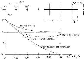
 INBOARD PLA TES. End plates have also been investigated in positions inboard the wing tips. Results are presented in the “due-to-lift” chapter of “Fluid-Dynamic Drag”. Results of a more recent analysis (17,e) are plotted in figure 20. Because of viscous interference in the four comers of such combinations (particularly on the upper side) the actual effect is much smaller, however, than theoretically predicted. For comparison, we have calculated a function, assuming that the outboard portions of the wing panels would be ineffective (as a consequence of “complete” flow separation). Real results may be expected to fall inbetween the two lines shown. Pylon – or strut-supported fuel tanks, say at 1/2 of the half-span of an airplane, can be considered also to be inboard end plates. As tested in (22,a) a 1% reduction of induced angle and induced drag can be found for a pair of tanks at 0.64 of the half-span, with a strut length (measured to the center of the tanks) of almost 5% of the wing span.
|
igure 20.The effective aspect ratio of a wing when moving a pair of end plates inboard. |
!-‘4 11. *.! ip і ice of tip tanks on wing characteristics: uі ‘I’bvoid, North American Aviation Rpt NA-1947-755.
b) Wind-Tunnel Tests. RM А5Г02, L8J04, L9J04.
! ) >’ Hiaracteristics, RAE TN Aero-2085 (1950).
(■- і i ‘и її, mi of wing-tip tanks: a> *b. Analysis, ARC C’Paper 147 (1952).
b) Weber. Wing and Body, ARC RM 2889 (1957).
C Loading, NACA RM L1953B18.
W2) P mu-^imported tanks or engine nacelles:
a) IVnpei. Fuel Tanks, NACA W’Rpt L-371 (1942).
b) RAW On Swept Wing, ARC RM 2951 (19*52).
(24) Cone ;.VSA) re-analysis of induced flow:
a) yorn-x sheet Deformation, TN D-657 (1961).
b) Induced Drag of Bent-Up Wing Tips, R-139 (1962). у Wmgs With Cambered Span, Rpt R-152 (1963).
d) Bending Moments of Wings as in (c), TN D-1505.
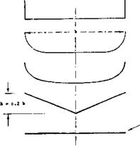
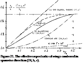
Cambered Span. The original induced-flow theory (1) applies to plane wings. A reanalysis (24) including shapes extending geometrically into the third dimension, points out possibilities of improving the efficiency of wings whose span ‘b’ (straight line between the tips) might be restricted. As shown in figure 21, the effective aspect ratio increases, meaning that induced angle and induced drag decrease, when cambering in spanwise direction. In comparison to a dihedraled wing having the same height ratio, the half-elliptical shape proves to be much more efficient. Of course, as in the case of end plates, the increased “wetted” area of cambered-span wings has to be taken into account when considering their “total” efficiency (in terms of L/D). Except for (a) all of the references under (24) deal with a reduction of the induced drag corresponding to (Aj/A) as in chapter VII of “Fluid-Dynamic Drag”. For practical purposes, we may assume that the induced angle of end-plated wings is one and the same for drag as for lift, expressed by:
da/dCL= dCD/dc£ (21)
Optimum lift distributions studied in (24) are essentially elliptical.
Bent-Up Tips. The result of equation (26) or figure 14, is also included in figure 21. End plates are seen to be more efficient than any continuous spanwise camber leading to the same height ratio. Up to h/b = 0.1, wing tips bent-up in the form of a quarter circle (24,b) are equally efficient, however. For example for A = 5, the corresponding bending radius would be 1/2 of the chord of a rectangular wing. As shown in chapter VIII of “Fluid-Dynamic Drag”, the interference drag in the corner of an 0010 airfoil bent up (or down) 90°, using a radius not larger than r =? 21, or = 0.2 c, is already zero (at zero lift). How large drag and loss of lift might be, say at the cruising lift coefficient of an airplaine, can only be determined by experiment. It is suggested, however, that with a bending radius between (0.2 c) and (0.1 b) as in the example above, interference would be small, and the effectiveness of a bent-up tip as an end plate would be high (might be the same as theoretically predicted). It is also expected that any bent-down wing tips (or suitably profiled end plates) would not have much of an interference drag.
|
Figure 22 Flow pattern past a wing tip, drawn on the basis of flow observations in a water tunnel (7,a). |
Trailing-Vortex Hazard. As discussed in the beginning of this chapter, the characteristics of the trailing vortex, figure 22 and Chapter XI, and its strength determine the hazard effects of large aircraft on other airplanes flying in the vicinity. These hazard effects are especially severe when there is a large spread in gross weight between the aircraft (25,a, c,d). It is thus desirable to alleviate the hazard by reducing the strength or breaking up the trailing vortices. The strength of the trailing vortices depends on the wing loading and thus in the far wake would be the same if all the energy is concentrated in the rolled up tip vortex. Thus, changes in distribution would be expected to have a small effect in alleviating the hazard. The use of part span trailing edge wing flaps, however, does apparently reduce the hazard by a change in lift distribution at a distance of 180 wing chords downstream (25,b). This is probably due to a reduction of the strength of the tipwortex by the generation of second vortex at the flap outboard edge. If the vortex at the flap outboard edge does not combine with the tip vortex, use of flaps may be a practical method of reducing the trailing-vortex hazard in the vicinity of airports.
|
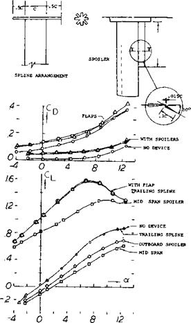
Figure 23. Effects of changes of lift distribution and trailing edge spoiler on lift and drag of a wing. |
A second way of reducing the problem of trailing vortices is by breaking up the rotational energy. To accomplish this a trailing spline as illustrated on figure 23 was tested as well as a spoiler. These devices were designed to break up the vortex and did show an improvement to 100 chords downstream; however, the improvement died out at the downstream distances corresponding to 180 chord lengths. It appears that such devices should be designed to take out the rotational velocity of the vortex to be effective. The trailing spline did not effect the lift of the wing but did increase the drag as shown on figure 23.
25. T Wing trailing-vortex hazard
a) McGowan, Trailing Vortices of Transport Aircraft, NASA TN-D-829.
b) Croorn, Trailing-vortex Hazard Alleviation Devices, NASA TN LX-3166.
c) Orloff, Vortex Measurements – Swept Wing Transport, JofA/C June 1974.
d) Brashers, Aircraft Wake Vortex Transport Model, J of А/С May 1974.
e) Chigier, Vortexes in Aircraft Wakes, Sci Amer, March 1974.
f) Donaldson, Vortex Wakes of Conventional А/С, AGARD – AR-204


