BEMT in Climbing Flight
The BEMT may be used to estimate the blade airloads during vertically climbing flight. This problem is of some interest because of the changes in the spanwise distribution in lift and so forth that take place. In climbing flight the BEMT requires the use of the Eq. 3.61, that is,
which in this case has been modified with the use of the Prandtl tip-loss factor. The numerical solution proceeds as before for the hovering rotor. However, notice that a solution for the blade pitch must also be obtained for each climb rate because thrust also equals weight in the climb (but neglecting airframe download and vertical-drag effects).
|
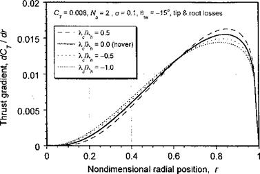
Figure 3.21 BEMT predictions of spanwise thrust for a two-bladed rotor with linear blade twist in vertically climbing and descending flight. |
Representative results are shown in Fig. 3.21 for both climbing and descending conditions at the same Ct compared to the hover result. The results show how the spanwise distribution of thrust becomes more heavily biased outboard in climbing flight, with the opposite effect in descending flight. This also changes the distributions of lift coefficient, torque, and so on. While the validity of the BEMT does not strictly extend to descending flight when moving from hover, for the same reasons that the simple momentum theory does not apply here, the solution has credibility as long as the descent velocities are small.
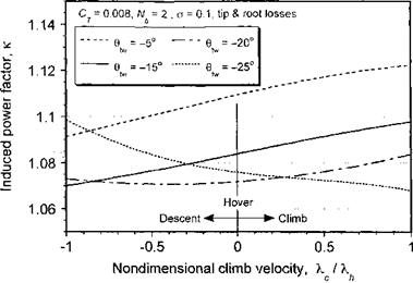
Because the climb (or descent) affects the spanwise distribution of airloads it is of interest to examine the changes in the induced power factor that take place. Normally it is acceptable to assume that к does not change with flight condition, but much has to do with the actual rotor design. Representative results are shown in Fig. 3.22 for the same rotor in climbing and descending flight but with different amounts of blade twist. The results are obtained by finding the induced power from the BEMT normalized by the induced power from the simple momentum theory. Clearly the value of к may increase or decrease with climb velocity, depending on the blade twist.
For a rotor that has close to ideal blade twist (which in this case is #tw ~ —20° at the defined operating condition of Cj — 0.008) either climbing or descending flight changes the spanwise distribution of airloads further from the ideal and the values of к increase. For a blade with less than near optimum twist, notice from the results in Fig. 3.22 how к actually decreases as the rotor descends compared to a rotor with large amounts of blade twist (such as a tilt-rotor). This has particularly important implications for the design of autogiro rotors (see Chapter 12); because the flow is upward through the rotor in autorotation little or no twist will give better efficiency (i. e., lower autorotative rate of descent, shallower aft disk tilt in level flight, and overall better lift-to-drag ratio for the rotor). For blades with large amounts of twist, it is apparent that к improves somewhat in a climb but increases more quickly in a descent. Overall, however, the results show that the variations of к with climb or descent velocity are fairly modest and for many forms of performance analyses it will be acceptable to assume that к =? constant.
|
Figure 3.22 BEMT predictions of induced power factor in vertically climbing and descending flight. |


