Bending
As in the case of torsion, the beam is initially treated as having nonuniform properties along the x axis. The x axis is taken as the line of the individual cross-sectional neutral axes associated with pure bending in and normal to the plane of the diagram in Fig. 2.5. For simplicity, however, we consider only uncoupled bending in the x-y plane, thus excluding initially twisted beams from the development. The bending deflections are denoted by v(x, t) in the y direction. The x axis is presumed to be straight, thus excluding initially curved beams. We continue to assume for now that the properties of the beam allow the x axis to be chosen so that bending and torsion are both structurally and inertially uncoupled. Therefore, in the plane(s) in which bending is taking place, the loci of both shear centers and mass centers must also coincide with the x axis. Finally, the transverse beam displacement, v, is presumed small to permit a linearly elastic representation of the deformation.
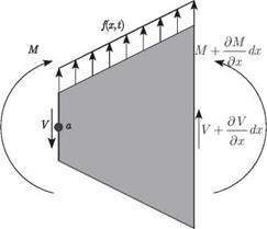
Equation of Motion. A free-body diagram for the differential-beam segment shown in Fig. 2.6 includes the shear force, V, and the bending moment, M. Recall from our previous discussion on torsion that an outward-directed normal on the positive x face is directed to the right, and an outward-directed normal is directed to the left on the negative x face. By this convention, V is the resultant of the transverse shear stresses

Figure 2.6. Schematic of differential beam segment
in the positive y direction (upward in Fig. 2.6) on a positive x cross-sectional face and in the negative y direction on a negative x cross-sectional face. In other words, a positive shear force tends to displace the positive x face upward and the negative x face downward, as depicted in Fig. 2.6. The bending moment, M, is the moment of the longitudinal stresses about a line parallel to the z axis (perpendicular to the plane of the diagram in Fig. 2.6) at the intersection between the cross-sectional plane and the neutral surface. Thus, a positive bending moment tends to rotate the positive x face positively about the z axis (in the right-handed sense) and the negative x face negatively about the z axis. This affects the boundary conditions, which are examined in detail in connection with applications of the theory in Chapter 3. The distributed loading (with units of force per unit length) is denoted by f (x, t). The equation of motion for transverse-beam displacements can be obtained by setting the resultant force on the segment equal to the mass times the acceleration, which yields
/ д V d2v
f (x, t)dx — V + I V +- dx I = mdx—2 (2.47)
V д x / д t2
and leads to
д V д 2 v
– + f(x.,) = m -2: (2-48)
where m is the mass per unit length, given by p A for homogeneous cross sections. We must also consider the moment equation. We note here that the cross-sectional rotational inertia about the z axis will be ignored because it has a small effect. Taking a counterclockwise moment as positive, we sum the moments about the point a to obtain
which, after we neglect the higher-order differentials (i. e., higher powers of dx), becomes
+ V = 0 (2.50)
д x
Recall that the bending moment is proportional to the local curvature; therefore
__ д 2v
M = EI w (2-51)
where EI may be regarded as the effective bending stiffness of the beam at a particular cross section and hence may vary with x. Note that for isotropic beams, calculation of the bending rigidity is a straightforward integration over the cross section, given by
where E is the Young’s modulus. When the beam is homogeneous the Young’s modulus may be moved outside the integration so that EI = EI where I is the crosssectional area moment of inertia about the z axis for a particular cross section. Here, the origin of the y and z axes is at the sectional centroid. However, when one or more of the constituent materials is anisotropic, determination of the effective bending rigidity becomes more difficult to perform rigorously. For additional discussion of this point, see Section 2.4.
Substitution of Eq. (2.51) into Eq. (2.50) and of the resulting equation into Eq. (2.48) yields the partial differential equation of motion for a spanwise nonuniform beam as
Strain Energy. The strain energy of an isotropic beam undergoing pure bending deformation can be written as
![]() (2.54)
(2.54)
This is also an appropriate expression for the bending strain energy for a composite beam without elastic coupling.
Kinetic Energy. The kinetic energy of a beam undergoing bending deformation can be written as
![]()
![]()
![]()
![]() (2.55)
(2.55)
just as for a vibrating string. For a spanwise nonuniform beam, m may vary with X.
Virtual Work of Applied, Distributed Force. The virtual work of an applied distributed force f (x, t) on a beam undergoing bending deformation may be computed as
S W = f f(x, t)8v(x, t)dx (2.56)
J0
just as for a vibrating string.


