Blade Element Analysis in Forward Flight
For a helicopter, the rotor must provide both a lifting force (in opposition to the aircraft weight) and a propulsive force (to overcome the rotor and airframe drag) in forward flight. In – forward flight, the rotor moves almost edgewise through the air, and the blade sections must encounter a periodic variation in local velocity (Fig. 2.1). This gives rise to a number of complications in the aerodynamics of the rotor, including the effects of blade flapping, significant compressibility effects, unsteady effects, nonlinear aerodynamics, and the possibility of stall, reverse flow, and so on, and the complex induced velocity from the rotor wake (see Chapter 10). All these effects are difficult to model. However, using the BET with certain simplifying assumptions, the leading terms of the rotor aerodynamic forces can be obtained – see Chapter 4. These solutions are very instructive and also provide closed form expressions that can be used for validation or as “sanity checks” when analyzing the results from more comprehensive mathematical models of the rotor aerodynamics. The use of such checks is considered good engineering practice.
3.5.1 Determining Blade Forces
The same blade element assumptions and approximations previously used for the axisymmetric flight case can also be considered as valid in forward flight. As before, the velocity at the blade element with a pitch angle в is decomposed into an out-of-plane (perpendicular) velocity component, UP, and a tangential (in-plane) component, Up, perpendicular to the leading edge of the blade, both relative to the rotor disk plane, as shown previously in Fig. 3.1. The resultant velocity is
because Up is generally small relative to Up over most of the blade. The relative inflow angle (or induced angle of attack) at the blade section is
![]() (UP Up
(UP Up
ф — tan 1 ( — ] ^ — for small angles.
Therefore, the aerodynamic AoA of the blade element is given by
a = в — ф. (3.164)
The resultant incremental lift dL per unit span on the blade element is given by
dL = ^pU2cCi dy = ^pUpcCia(6 — ф) dy
![]() = ipt/|cCZa ^0 – dy = іpcCia{0U} – UPUT) dy
= ipt/|cCZa ^0 – dy = іpcCia{0U} – UPUT) dy
and the incremental drag is
dD = – pU2cCd dy, (3.166)
which act perpendicular and parallel to the resultant flow velocity at the section, respectively. Resolving these forces perpendicular and parallel to the rotor disk gives
1
dFz = dL cosф — dDsintj) ~ dL = – pcCia(9Uj — UpUj) dy (3.167)
and
dFx — dL sin ф + dDcoscf) & (f)dL + dD
= pcCi. (eUpUT – Uj + ^tutJ dy – (3-168)
In forward flight the blade element velocity components are periodic at the rotor rotational frequency. As for the hover case, there is an in-plane velocity component because of blade rotation about the rotor shaft, but now there is a further free-stream (translational) part such that
Ur(y, Ф) = &У + Voo sin ф = Qy + [jlQR sin ф. (3.169)
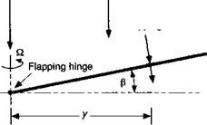
The out-of-plane component consists of three parts. The first is a component comprising the inflow velocity, as in the hover case. The other two components result from perturbations in velocity at the blade element that are produced by blade motion (i. e., flapping). With reference to Fig. 3.26, a perturbation in velocity yfi is produced as a result of the blade flapping velocity about a hinge, with another perturbation (xQRfi cos ф produced because of blade flapping displacements (coning). The origin of blade flapping is considered in detail in Chapter 4. Therefore, the velocity perpendicular to the disk can be written as
Up(y, ф) = (Ac + Xi)QR + у$(ф) + p,£lRPty)cos ф. (3.170)
Also, there is a radial velocity component parallel to the span axis of the blade and this is given by
ІІіі(ф) = /jlQR cos ф. (3.171)
In the BET the aerodynamic effects resulting from this radial velocity are neglected. This is in accordance with the independence principle of sweep, which states that the aerodynamics result only because of the velocity components and AoA perpendicular to the leading edge
![]()
![]()
 Flapping rate induced velocity, у 6
^Direction of positive flapping
cosi|)
In-plane radial velocity, iQR cos-ф
of the blade (see discussion in Chapter 9). However, the effects of the radial velocity component along the blade may need to be considered when estimating the rotor drag.
In nondimensional form, the three preceding equations can be written as
![]()
 (3.172)
(3.173)
(3.174)
3.5.2 Definition of the Approximate Induced Velocity Field
Besides accounting for the effects of blade pitch and flapping motion, the blade element method in forward flight requires an estimate of the induced velocity field, which is no longer axisymmetric. This is not known a priori because it is based on a knowledge of the rotor wake (Chapter 10), which in turn depends on the rotor thrust, the blade flapping and overall trim state (i. e., blade collective and cyclic pitch angles), and the distribution of airloads over the blades. The effects of the individual tip vortices tend to produce a highly nonuniform inflow over the rotor disk, and the calculation of these effects is a formidable undertaking. Nevertheless, the performance of the rotor can be analyzed with the aid of simpler models that represent the basic effects on the inflow resulting from the rotor wake. These models are called “inflow” models and can be formulated on the basis of experimental results or more advanced vortex theories. Because of their simplicity, inflow models have found great utility in many problems in helicopter rotor aerodynamics, aeroelasticity, and flight dynamics.


