Our heavyweight helicopter equal in the world does not have
In Rostov started production of the most load-lifting rotary-wing car The Russian holding «Helicopt[...]

Everything about aircrafts and helicopters. News and events in aviation worldwide. Civil, transportation, military helicopters and airplanes.

Everything about aircrafts and helicopters. News and events in aviation worldwide. Civil, transportation, military helicopters and airplanes.

Everything about aircrafts and helicopters. News and events in aviation worldwide. Civil, transportation, military helicopters and airplanes.

Everything about aircrafts and helicopters. News and events in aviation worldwide. Civil, transportation, military helicopters and airplanes.


The Lift on a Blade Element
The momentum method gives much insight into conditions at the rotor and in the wake, but it does not deal with the actual development of thrust—that is, the lift on the individual blade elements. The mechanism by which lift is developed by an airfoil is explained in textbooks on airplane aerodynamics, and that explanation applies just as well to an element of a rotor blade as to a section of a wing.
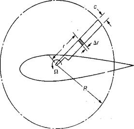
The geometry of a blade element is shown in Figure 1.5. A blade element is one small portion of the blade a distance, r, from the center of rotation with a spanwise dimension, Ar. The increment of lift, AL, on this blade element is:
AL = q СісАг
|
The local dynamic pressure, q, is a function of the velocity due to rotation at the blade element. This velocity is zero at the center of rotation and increases linearly to the tip. To express this velocity, it is convenient to use the rotational speed in terms of radians per second, ft. The local velocity at the blade element, V/} is:
V{= ftr ft/sec
At the tip, the tip speed, VT, is:
FT = ClR ft/sec
Tip speeds on modern helicopters are selected to be as high as they can be without encountering compressibility effects on the advancing blade in forward flight. These effects will be discussed in more detail in Chapter 3. At this point, it is enough to state that design tip speeds on both the main and tail rotors fall in the region between 500 and 800 ft/sec. Since tip speeds fall into this rather narrow band, it is usually more convenient in studying rotor aerodynamics to use this as a parameter to measure rotor speed rather than rpm, which will vary widely with rotor size. Note that
The local dynamic pressure, q, at the blade element is:
y = {p(Clr)2
The local lift coefficient, ch may be written as:
Ci = a a
where a is the local angle of attack in radians, and a is the slope of the lift curve per radian. Since the actual angle of attack including induced effects will be used, the correct lift curve slope is that corresponding to a two-dimensional airfoil. Conventional airfoils at low Mach numbers have lift curve slopes of approximately 0.10 per degree or 5.73 per radian. This value increases slightly with Mach number and will be assumed to be 6.0 for use in this type of simple rotor analysis.
The local angle of attack is determined by the geometric pitch of the blade, 0, and the local inflow angle, ф, as shown in Figure 1.6.
a = 0 – ф
The inflow angle, ф, is defined by the two mutually perpendicular velocities, fir and vly such that:
ф = сап"^
If ф is less than 10° — and it is for most of the rotor—then the small-angle assumption may be used:
 |
 |
ф = radians llr
FIGURE 1.6 Orientation of Blade Element and Local Velocities
Thus the local angle of attack is:
a = 0 — rad Пт-
and
![]() ct = a I 0 —
ct = a I 0 —
The increment of lift on the blade element is:
AL = – (Пг)2<г f 0 — j cAr