Control Force per g
From (2.8,4) we get the incremental control force
AP = GSecehpV2 AChe (3.2,1)
Che is given for rectilinear flight by (2.5,2). Since it too will in general be influenced by q, we write for the incremental value (AS, = 0)
A Che = Clu, nAa + Cheqq + b2ASe (3.2,2)
|
AC*. |
The derivative Ch is discussed in Sec. 5.4. Using (3.1,4) and (3.1,6b), (3.2,2) is readily expanded to give
From (2.6,46) we note that the last parenthetical factor is b2C’LJCLa or b2a’la. For ASe we use the approximation (3.1,9) in the interest of simplicity and the result for A Che after some algebraic reduction is
In keeping with earlier nomenclature, h’m is the control-free maneuver point and (h’m — h) is the corresponding margin. On noting that CwpV2 is the wing loading w, we find the control force per g is given by
AP a’b2
Q = —— Г = ~GSecew —— (2ц – CL)(h – h’J (3.2,6)
n — 1 Ipudet
Note that this result applies to both tailed and tailless aircraft provided that the appropriate derivatives are used. The following conclusions may be drawn from (3.2,6).
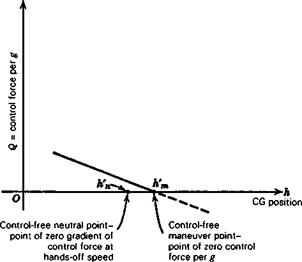
1. The control force per g increases linearly from zero as the CG is moved forward from the control-free maneuver point, and reverses sign for h > h’m.
2. It is directly proportional to the wing loading. High wing loading produces “heavier” controls.
3. For similar aircraft of different size but equal wing loading, Q Sece i. e. to the cube of the linear size.
4. Neither CL nor V enters the expression for Q explicitly. Thus, apart from M and Reynolds number effects, Q is independent of speed.
5. The factor ц which appears in (3.2,5) causes the separation of the control-free neutral and maneuver points to vary with altitude, size, and wing loading, in the same manner as the interval (hm — hn).
Figure 3.3 shows a typical variation of Q with CG position. The statement made above that the control force per g is “reversed” when h> h’m must be interpreted cor-
|
Figure 3.3 Control force per g. |
rectly. In the first place this does not necessarily mean a reversal of control movement per g, for this is governed by the elevator angle per g. If h’m < h < hm, then there would be reversal of Q without reversal of control movement. In the second place, the analysis given applies only to the steady state at load factor n, and throws no light whatsoever on the transition between unaccelerated flight and the pull-up condition. No matter what the value of h, the initial control force and movement required to start the maneuver will be in the normal direction (backward for a pull-up), although one or both of them may have to be reversed before the final steady state is reached.
CONTROL-FORCE GADGETS
The control forces on a manually controlled airplane can be made to deviate from the “natural” pattern that flows from the size of the airplane, the aerodynamic design, and the speed and altitude of flight without necessarily using either powered controls or aerodynamic tabs (see Sec. 2.7). Some “gadgets” that can be used to this end are springs, weights, and variable-ratio sprockets and linkages. These can have the effect of modifying the control-force to trim and the control-force per g, giving the pilot the same feel as if the control-free neutral and maneuver points were moved. Some details of these effects are given in Sec. 7.1 of Etkin (1972).


