Evaluation of the Aerodynamic Damping
Due to the fact that the cascade in the "flitter case" remains aeroelastically stable for very small pitching amplitudes (below 0.2°) it was possible to obtain unsteady pressure distributions caused by forced pitching vibrations of the blades in each traveling wave mode — in the same manner as the larger amplitudes in the "transonic reference case".
Following the "aerodynamic aproach" the measured unsteady pressure values and vibration signals were recorded. A Fourier transformation yields the first harmonic of the pressure which is related to the pitching motion of that blade і according to eq. (2) by
![]()
![]() p(t) = p COS(Ш — І (7/t. + Ф) .
p(t) = p COS(Ш — І (7/t. + Ф) .
The unsteady pressure coefficient is defined as
a =_______ I____
P 6: (p, i – Pt )
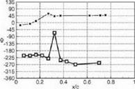
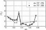
where p — p ехр(у’Ф) is the first harmonic of the unsteady pressure. The Cp-distribution for the interblade phase angle (IBPA) Of. = 72° is shown in Figure 8a for the "transonic reference case" and in Figure 8b for the "flitter case". Tn order to avoid numerical inaccuracies due to the discrete Fourier transformation, the sinusoidal vibration signals were Fourier transformed as
![]()
|
|
||
|

Figure 8a. Unsteady pressure coefficient C’p for the IВ PA о = 72° of the transonic reference case (magnitude at the top. phase at the bottom)
well. Arranging the Cp-distribulions of each IB PA side by side, Figures 9a and 9b are obtained.
It can be seen from the pressure distribution of both cases, that the impulse response of the front shock is visible on the suction side at xjc 0.28 in the "transonic reference case" and at xjc « 0.32 in the "flitter case". Comparing the channel shock of the "transonic reference case" with the "flitter case", the impulse response on the pressure side is visible at xjc se 0.17 in the "transonic reference case" and at xjc % 0.32 in the "flitter case". The impulse response of the channel shock is only visible at the suction side at xjc > 0.75 for the "flitter case".
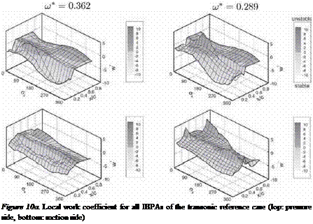
The contribution of the locally acting aerodynamic forces due to the unsteady pressure to the aerodynamic damping of the cascade is given by the local work coefficient, i. e. the dimensionless work per unit arc length performed by the fLiid on the blades. It is obtained by the integration with respect to time t over one period T of the pitching motion a(t) and yields
w*(0 = / ср(Л’t) ~i] [№)-П)) x n(0]3<it./o °
|
Figure 9b. Unsteady pressure coefficient Cp for all IBPAs of the flitter case (top: pressure side, bottom: suction side)
where (f(0—f0) is the dimensionless vector from the pitching axis to a surface point at the dimensionless arc length £ and n(£) as the outward normal vector on that surface point. The subscript "3" denotes the radial component of the cross product. For the pitching motions of rigid blades in a given traveling wave mode, the local work coefficient is dependend on the amplitude of the aerodynamic moment due to the first harmonic of the unsteady pressure on a surface location, the (harmonic) pitching motion of that blade, and the phase between them to a local stability parameter. It is negative for stable and positive for unstable aerodynamic conditions.
In order to assess the aerodynamic stability of the two transonic cases in detail, the local work coefficient u;*(£) is used to acquire an insight into the local contributions of the unsteady pressure at each measuring location —especially at locations, where considerable pressure fbetuations appear due to the shock movement, which is caused by the blade vibration. Regarding Figure 10a for the "transonic reference case" and Figure 1 Ob for the "flitter case", the following aspects are recognizable:
■ The contribution of the high unsteady pressure level on the leading edge stabilizes the pitching motion of the blade for all traveling wave modes. On the suction side, the local work coefficient is nearly constant, on

Figure 10b. Local work coefficient for all IBPAs of the flitter case (top: pressure side, bottom: suction side)
the pressure side, the stabihzing effect of the leadling edge for traveling wave modes with an ШРА between 180° and 360° is higher then for IBPA between 0° and 180° .
■ The high unsteady pressure level due to the front shock is stabilizing the motion in all travelling wave modes except for those with an IBPA between 288° and 360° for the "transonic reference case". Here the local work coefficient is near zero, that means no significant contribution to stability or instability. In contrast to that, the shock impulse of the front shock stabilizes only for the IBPA between 36° and 180° in the "Hiller case" — for the other traveling wave modes it destabilizes.
■ Comparing the channel shock impulse on the pressure side, in both cases the largest contribution to instability occurs in the vicinity of an ЮРА of 126°, but at a higher level for the "flitter case" Regarding the contribution of the front shock impulse on the suction side, this effects may cancel each other out.
■ The most significant difference between the two cases is the strong channel shock impulse on the suction side in the "flitter case". Due to its
position near trailing edge and the large moment arm, its contribution is very strong:
– to the stability for the IBPAs between 180° and 360° and between 0° and 18°
– and to the instability for the IBPAs between 36° and 162° with a strong jump between stability at 18° and instability at 36° .
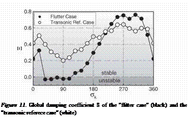
In order to assess how these contributions affect the flitter behavior of the cascade, a global damping parameter was evaluated as follows: With the definition of the unsteady pressure coefficient according to eq. (6), the unsteady moment coefficient Cm is calculated. Using the imaginary part, the global damping coefficient is defined as

A positive value of S represents stability with damped oscillations; negative values indicate instability.
It can be seen, that in both cases the traveling wave modes with the lowest aerodynamic damping occur at IBPA near 90° . Especially for the flitter case, the aerodynamic damping for IBPA between 36° and 108° is negative, i. e. if the structural damping could not compensate this aerodynamic instability, the cascade starts to flutter.


