EXAMPLES FOR THE UNSTEADY BOUNDARY CONDITION
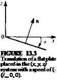
As a first example, let us investigate several simple motions and the corresponding derivation of the boundary conditions. Consider a flat plate at an angle of attack a moving at a constant velocity (4 in the negative X direction, as shown in Fig. 13.3. The translation of the origin is
V0=(*0, Y„,Z0) = (-t/., 0, 0)
and the rotation is
ft = 0
The vector n on the flat plate and in the body frame is
n = (sin a, 0, cos a)
Substituting these values into the boundary condition (Eq. (13.13a)) results in
/ ЭФ ЭФ
 |
||
(УФ – V0 – ft X r) • n = I — + t4, 0, — I • (sin a, 0, cos ar) = 0
FIGURE 13.4
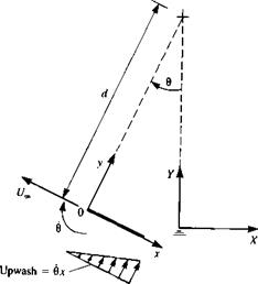
 Motion of a flat plate along a circular arc with radius d.
and by assuming that a « 1 this reduces to the classical result
ЭФ / ЭФ
— =-U„ + —)ana~-U,*a (13.30)
For the second example, consider a one-degree-of-freedom motion of a flat plate along a circular arc (Fig. 13.4) with a radius of d. If the origin ( )0 is moving with a speed of U„, then
(X<>, Y0, Z„) = (-U,» cos в, 0, l/„ sin в)
But it is easy to observe that V0, at any moment, resolved in the direction of the (x, y, z) system will be
V0 = (-f4, 0, 0)
The rotation is
П = (0, в, 0)
where
and
Я X r= (0z, 0, — вх)
Also, the normal is n = (0,0,1). The boundary condition for a flat plate (at
zero angle of attack in its coordinate system) is then
(УФ – Vo – Я x r) • n = – flz + IL, 0, — + вхJ • (0, 0, 1) = 0
which results in
ЗФ. x
– — „—u.. («.31,
Note that there is an upwash of w = вх due to this motion (see Fig. 13.4), resulting in lift (even though a = 0 in the flat plate’s coordinate system). Also, it is clear from this example that if the airfoil leading edge is placed at x = – c then instead of an upwash the airfoil will be subject to a downwash (or negative lift). Therefore, the location of the rotation axis is very important in motions with body rotations.
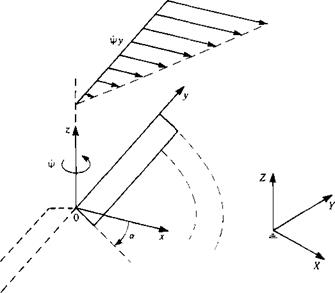
Next consider the rotation of a helicopter rotor in hover (Fig. 13.5) at a rate rj>. For this case,
V0 = (0,0,0)
Я = (0,0, V»)
Я X r = (-і/>у, 0)
n = (sin a, 0, cos or)
|
FIGURE 13.5 Description of the motion of a helicopter rotor in hover. |
The boundary condition for a flat plate rotor, at an angle of attack a, is
, /ЭФ ЭФ. ЭФ
(VO – V0 – Я X r) • n = (— + фу, ——– фх, —) • (sin a, 0, cos a) = 0
dx ay dz)
which results in
 (13.32)
Note that to the rotor blade sections the oncoming velocity seems to increase with the radius |y|, and consequently most of the loads will be generated close to the tips.
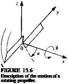
 Similarly, the boundary condition for a statically spinning propeller blade can be established by rotating the blades at a rate ф about the x axis as shown in Fig. 13.6 (observe the definition of a in Fig. 13.6 for this example).
V0 = (0,0,0) Я = (<*>, 0, 0)
Si X r = (0, — фг, фу) n = (sin a, 0, cos a)
and a is defined here in a similar manner to the wing at angle of attack. The boundary condition for a flat propeller blade is
/ЗФ ЭФ • ЭФ.
(VO — V0 – Я X r) • n = I ——, — + фг, —– фу)’ (sin a, 0, cos a) = 0
V dx ay dz J
which results in
 (13.33)
 |
 |
Again, most of the load will be generated at the tips where фу is the largest. Also, if the propeller advances at a speed of CL, parallel to its x axis,
then the boundary condition becomes


