Implementation of the Inclinitation Sensor
For an automatic evaluation by the flow solver of the boundary layer thickness, the grid stretching ratio and the skewness near the wall, the boundary layer had to been scanned at every grid point on the surface. For this, the neighboring point furthest from the wall was detected, starting at each surface point and working in the wall normal direction. In this manner the entire boundary layer is traversed until the total pressure reaches 99.9% of the free stream total pressure [2]. The skewness of the grid is defined as the average deviation from the wall normal vector and the stretching ratio as the maximum stretching ratio found inside the boundary layer. These quantities are saved at the respective surface points. From the results of the test computations for the isolated error mechanisms the magnitude of the expected error was determined. The friction coefficient at the positions x1…x4 was computed
|
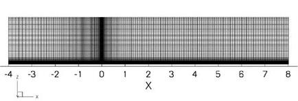
Fig. 1 Structured grid of the flat plate test-case with 52,000 grid points |
and compared by normalization with the results of the reference grid. The error factor of Cf is therefore given by
and the percentage error as Cfn ■ 100%. This was carried out for all four stream – wise positions to verify independence of this variable. For the prediction of the errors in cf the skewness is assumed as constant. The error factor cfn was parameterized with a 3rd order polynomial (p(x) = a0 + a]_x + a2x2 + a3x3 ) and the coefficients ai were identified for all investigated models.


