Investigated Flow Cases
The aim of the experiments was to investigate the behavior of a cascade running into flitter. In order to decrease the reduced frequency
* о / cred / A ч
U) — Z7T —- (4)
Vi
with respect to the same infbw velocity v i the cascade was tuned to a lower torsional blade eigenfrequency. So it was possible to investigate an unstable aeroelastic condition at a transonic fbw case, which had been previously investigated.
|
Table 1. Steady upstream and downstream fbw parameters
|
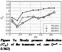
The transonic fbw condition is characterized by the occurrence of a front shock at x/c & 0.25…0.35 and a channel shock at x/c & 0.65…0.85 on the suction side and at x/c & 0.25…0.35 on the pressure side (Fig. 7b). In – and out-fbw parameters are mentioned in Table 1. Releasing the hydraulic brake at this fbw condition, it was possible to set the blade assembly to controlled pitching oscillations around midchord for each interblade phase angle and to measure the unsteady pressure distribution up to a pitching amplitude of approximate 0.1° in order to determine the aerodynamic damping following the "aerodynamic approach". The excitation frequency of 177 Hz was choosen slighly below the eigenfrequency of the blades in order to distuinguish forced and free vibrations in the frequency range. This excitation frequency corresponds to a reduced frequency cj* = 0.289. Exceeding this amplitude the cascade starts to vibrate with a frequency of 182 Hz (“Flutter Case” Table 1).
 |
 |
With the same cascade, an aerodynamic damping investigations was performed following the "aerodynamic approach" with each blade tuned to a higher eigenfrequency and excited at 215 Hz (cc* = 0.362). Here the cascade remained aerodynamically and aeroelastically stable (‘Transonic Reference Case” Table 1).
Figure 7b. Steady pressure distribution (Cp) of the Hitler case (w * — 0.289)


