Prandtl’s Tip-Loss Function
The idea of a tip-loss factor, В, has already been introduced. Instead of assuming a value for В it is possible to compute tip-loss effects on the basis of a method devised by Prandtl – see Betz (1919). Prandtl provided a solution to the problem of the loss of lift near the tips resulting from the induced effects associated with a finite number of blades. This theory contains all the elements of a model that was developed later by Goldstein (1929) and Lock (1930) but has several simplifications that make it attractive for helicopter rotor analysis. Prandtl replaced the curved helical vortex sheets of the rotor wake by a series of 2-D vortex sheets, the assumption here being that the radius of curvature at the blade tips is large. This is a satisfactory assumption for helicopter rotors but is less so for propellers.
Prandtl’s final result can be expressed in terms of a correction factor, F, where
(3.120)
where / is given in terms of the number of blades and the radial position of the blade element, r, by
![]()
 (3.121)
and ф is the induced inflow angle (= X(r)/r).
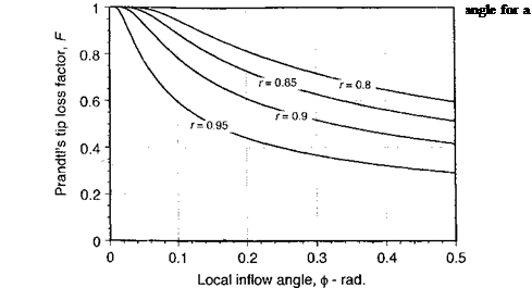
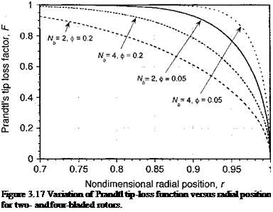
Prandtl’s F function is plotted in Fig. 3.16 versus the local inflow angle, <p, for a two – bladed rotor. The basic effect of the F function is to increase the induced velocity over the tip region and reduce the lift generated there. The Prandtl function is, therefore, sometimes referred to as a “circulation loss” function. Prandtl’s F function is plotted versus the radial position of the blade element in Fig. 3.17 for two – and four-bladed rotors, and for different values of the inflow angle, ф. The gradual reduction in the function as the tip is approached represents the basic induced effects of the vortex wake. Notice that F is a function of the number of blades and always has lower values for rotors with fewer blades. This is because the total bound circulation is distributed over fewer blades and the induced effects in the rotor wake are higher. For the limiting case where Nb —> oo, which approximates an actuator disk, the circulation is distributed uniformly over the disk and F —> 1.
In the application of the Prandtl tip-loss method, the function F can also be interpreted as a reduction factor applied to the change in fluid velocity as it passes through the control volume. The tip-loss effect can be incorporated into the BEMT as follows. For hovering flight Eq. 3.44 is now modified by the use of the Prandtl factor, F, to give
![]()
 |
dCr = 4FX2r dr.
 |
Also, from the BET it has been shown previously that
dCT = {Or2 – kr) dr. (3.123)
Equating the incremental thrust coefficients from the momentum and blade element theories gives
(Qr2 – kr) = AFk2r (3.124)
or
9 /oCi oCi
1 + (lF ) * “ 1Г*Г = °- <ЗЛ25)
This quadratic has the solution
Because F is a function of k, this equation cannot be solved immediately because к is initially unknown. Therefore, it is solved iteratively by first calculating к using F = 1 (corresponding to an infinite number of blades) and then finding F from Eq. 3.120 and recalculating к from the numerical solution to Eq. 3.126. Convergence is rapid and is obtained in three or four iterations.
The resulting effect of the application of PrandtTs F function on the blade-thrust distribution is shown in Fig. 3.18 for an untwisted blade. These comparisons have been performed at the same value of thrust obtained without using the tip-loss effect. Notice that the primary effect of the tip loss is to reduce the thrust production over the immediate tip region. This loss of thrust has to be compensated by a slightly greater blade pitch, which increases the angles of attack further inboard to produce the same total rotor thrust. Generally it is found that the use of a larger, number of blades tends to improve the efficiency of the
rotor (increases the figure of merit) for a given solidity and disk loading because the induced tip-loss effects tend to decrease with increasing number of blades (see Questions 3.2 and 3.3).
The ideas of tip loss can also be extended to model the loss of lift at the root of the blade. In this case the value of / in Eq. 3.120 becomes
![]() (3.127)
(3.127)
The tip and root losses can be combined into a single function using
![]() / = /root /tip,
/ = /root /tip,
where /root is given by Eq. 3.127 and /tip by Eq. 3.121. Generally the effects of including root loss effects are small on the calculation of total rotor thrust and power because the inboard parts of the blade operate at relatively low dynamic pressures. However, the effects are usually more apparent when examining the spanwise distribution of airloads in coefficient form.
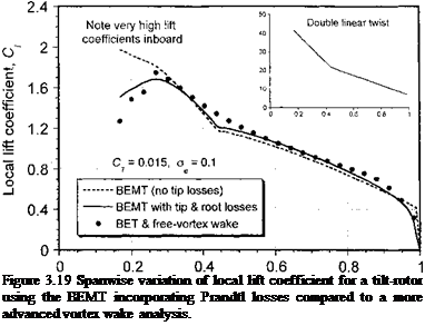
An example using the BEMT with both tip and root losses is shown in Fig. 3.19 for the case of a tilt-rotor operating in the hover mode. Tilt-rotor blades have large amounts of twist, which are more optimal for forward flight performance in propeller mode compared to helicopter mode. The results in this case show how the inboard sections of this rotor operate at relatively high lift coefficients compared to a typical helicopter (see the results in Fig. 3.8) and so more accurate nonlinear aerodynamic modeling here is important in this case, despite the lower dynamic pressures. The BEMT results are compared in Fig. 3.19 with the results of a more advanced blade element theory (BET) combined with a free-vortex model of the rotor wake (see Section 10.7.6). Clearly the use of the BEMT by itself gives reasonable agreement with the BET results, but the introduction of the Prandtl tip – and root-loss effects into the BEMT clearly gives much better results. (The results are all compared at the same total Cj ) Remember that the purpose of the Prandtl tip-loss function is to approximately model the high induced losses produced by the trailing vorticity generated from the tip and
Nondimensional radial position, r
 |
root side edges of the blade, flow physics that are included in the more advanced vortex wake model. Overall the results in Fig. 3.19 show that the BEMT is an effective tool for at least the preliminary analysis of the spanwise distribution of airloads, especially bearing in mind the negligible computational cost of this type of method.


