The Optimum Hovering Rotor
Minimum induced power requires uniform inflow over the disk. The corresponding condition for minimum profile power requires that each blade station operate at the AoA
for maximum Ci/Cd (i. e., at a, = oq as shown in Fig. 3.9). For minimum induced power then 9 — 9щ/г, and if each element of the blade is to operate at aq then
![]() (3.94)
(3.94)
Also, it has been shown previously from the BEMT that for an annulus of the disk
![]() dCj — 4A.2r dr.
dCj — 4A.2r dr.
Equating Eqs. 3.94 and 3.95 and solving for A gives
which is constant over the disk, as required. If it is assumed that oq is the same for all the airfoils along the blade span and independent of Reynolds number and Mach number, then for uniform inflow the product or in Eq. 3.96 must be a constant, that is,
![]()
![]() (3.97)
(3.97)
which requires a local chord distribution over the blade to be given by
Therefore, for each section of the blade to operate at the optimum lift-to-drag ratio, the local blade solidity, o{r) or blade chord, c{r) must vary hyperbolically with span, as shown by Fig. 3.11. Clearly this distribution is physically unrealizable but can be adequately approximated by a linear taper over the outer part of the blade. Because of the hub and root cut-out, the chord variation as r —> 0 does not matter anyway. Furthermore, as seen from Fig. 3.9, operating the airfoils at angles of attack that are few degrees less or greater than «і does not result in a serious degradation of C//C^. Therefore, the use of some planform taper, while not exactly hyperbolic or applied over the whole blade, will generally always have a beneficial effect on hovering rotor performance.
Optimum taper
Linear taper approximation
(same tip chord)
Figure 3.11 Radial distribution of blade chord for an optimum rotor and a linear approximation.
0. ![]()

2 0.4 0.6 0.8
Nondimensional radial position, г
Figure 3.12 Effect of blade taper on the lift coefficient distribution over a blade with constant twist.
![]()
|
thrust-weighted solidity. For a linearly tapered blade, this means that the solidity at 75% blade radius is the same in all cases – see Section 3.4. Without taper the lift coefficients at the root of the blade are relatively high and cannot operate at the best Ci/Cd ratio for the airfoil section so Cp0 would be higher than otherwise possible. As СУ is increased, the rotor performance will be limited by the onset of stall at the blade root. From Fig. 3.12 we see that with the introduction of a moderate amount of taper the values of Ci become much more uniform, with the values of С/ being significantly reduced at the blade root along with a mild increase in Q at the tip. This reduces the profile power component, and so the rotor can be operated at the same thrust but with an improved figure of merit.
 |
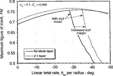
The point is expounded further by the results shown in Fig. 3.13, where the figure of merit is plotted versus the twist rate for a rotor with rectangular blades and one with linearly tapered blades. A mild amount of taper clearly gives a notable increase in FM. In either case, the rotor ultimately becomes limited by the onset of stall, but the use of blade taper clearly allows the rotor to operate with a higher stall margin. This also allows a higher possible collective pitch, a higher attainable rotor thrust, and better overall hovering efficiency.
so that
|
oCl. QnR1 Hip 2Nb |
|
|
|
|
confirming that ideal twist gives uniform inflow, a linear distribution of lift (thrust) and a constant “bound” circulation over the blade.
A link can also be made between the momentum theory of lift and the vortex theory (considered in Chapter 10). With a uniform circulation along the blade span, Helmholtz’s theorem requires a, single vortex of the same strength to trail from the blade tips. This vortex strength can be related to the blade loading as follows. The lift per unit span along the blade is
![]() dL — /0(£1у)Г dy.
dL — /0(£1у)Г dy.
Because Г is constant, then the lift on one blade is
L = par f у dy — pQFRz/2.
Jo
The total rotor thrust is T = A^L, and in coefficient form we have С
T 2(ttR2)Q‘
Using the result for the solidity that a — Nbc/nR, we get CT _ Г о 2 QcR
Г = 2£2Rc 1 ^ ) ,
|
|
|
|
|
|
|
![]()


