Wings with near-planar vortex wakes
3.2 . To begin with, we assume that the trailing vortex sheet, including its rolled-up edges, has ceased to grow in space or in time when it reaches the Trefftz plane. Otherwise, the general relation (3.2) would have to include the appropriate time-dependent terms.
This assumption can never be strictly true in an inviscid flow, but we may be content with the assurance that any growth is so slow that it can be neglected. In any case, viscous effects may have modified the structure of the vortex sheet and its flowfield, and we are prepared to ignore these, too. We may then assume that the vorticity vector in the sheet lies along the direction of the mainstream. The sheet takes no forces and hence intersects the Trefftz plane at right angles. It follows that the sheet induces only lateral velocity components, a sidewash Vyxr and a downwash vz^r, and that vx ■ 0 in the Trefftz plane. This leads to important simplifications if we also make use of the fact that some of the integrals over the sidepanels in (3.7) and
(3.8)
can be made to vanish if we make the further assumption that the velocity perturbations are smalt. The sidepanels may then be moved out far enough for square terms in the perturbation velocities to be so small as to make no contribution. Thus the integrals involving vz^ and vzv in the second term of (3.7) vanish; similarly, the whole of the second term in (3.8) vanishes. The expressions for the lift and drag forces from (3.7) and (3.8) now take the form
We note that the lift force is associated with the downwash in the Trefftz plane and with pressure differences over the horizontal sidepanels, whereas the drag force is manifested as a pressure integral over the Trefftz plane.
Next, we use the gasdynamic equations for the relation between pressures and velocities, in particular, Bernoulli’s equation (2.12) for perfect gases. For small perturbations, the leading terms in a power series of these perturbations are
p/p0 = 1 – Mq2 vx/Vq. (3.12)
For the flow considered, p = pq in the Trefftz plane, according to (3.12), since vx = 0. Thus the Mach number does not appear explicitly in the relations for lift and drag, even though the flow is assumed to be compressible. (3.11) and (3.12) can be inserted in the first term of (3.9). In the second term of (3.9),
P " Po “ – Pqvovx at z = ±A,
 |
||||
according to (3.11), to a first order. The relation for the lift then becomes
This can be further simplified if we introduce the perturbation velocity potential ф(х, у,г), analogous to (2.1). (3.13) can then be written as
+B
L = PqVq I" Аф (y)dy, (ЗЛ4)
-В
where Дф * фц – фд is the difference between the potential functions on the two sides of the trace of the trailing vortex sheet in the Trefftz plane. Thus the load over the body is related directly to the potential difference across the vortex sheet which the body leaves behind.
The pressure difference p – pQ in the Trefftz plane, which appears in (3.10) for the drag, can be approximated by
P – P0 “ – *Po(vy2 + vz2> >
according to (3.11). The relation for the drag then becomes
+A +B
D * ip0 I I [vy + vz] dydz ’ (3.15)
-A -B x““
which can be rewritten as
5 ‘ h°l І [(^) *(&)] ^ • <3-’6>
where the velocity potential is introduced again. Next, we assume that 3vx/3x is also zero in the Trefftz plane, in addition to vx _ 0, so that ф obeys the potential equation also for a hypothetical twodimensional flow in the Trefftz plane:
3jt+ „ о, (3.17)
2.2
3y 3z
which is a special form of (2.28). Further, we apply Green’s theorem to replace the double integral in (3.16) by a contour integral over the outer
surface of the trace in the Trefftz plane. We then have
![]() (3.18)
(3.18)
where n is normal to the trace and о is along it.
With (3.14) and (3.18), we have expressed both the lift force and the drag force in terms of the values of the velocity potential at the trace of the trailing vortex sheet in the Trefftz plane. If we know the shape of the trace, we can determine the potential function along it and then derive a direct relation between lift and drag on the body. The actual calculations are still rather complicated (see e. g. A Robinson & J A Laurmann (1956)); an instructive case has been treated by J H В Smith (1960). Further subtleties arise from the fact that the drag is a second-order quantity. W R Sears (1974) has pointed out that, strictly, it is necessary to account for the first-order downward deflection of the vortex wake but that, when this is done, the classical results derived here remain true, as it happens. Sears’s short paper should be studied carefully to understand fully the implications of the Trefftz-plane concept.
 |
 |
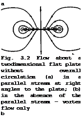
This lift-dependent vortex drag has a minimum value for a wing of given overall lift and span when the downwash vzTr “ – v in the Trefftz plane is constant along the trace of the trailing vortex sheet, as was shown by MM Munk (1919). For that case, the potential function ф(у, г) in the Trefftz plane can be determined by considering the trace as a solid body put into a twodimensional parallel flow with the velocity vz^r far below it. A simple and important particular solution is obtained when the trace is assumed to be a straight line at z = 0, extending from у = – s to у = +s. The flow
is then like that sketched on the lefthand side of Fig. 2.14(b) and is shown
(3.19)
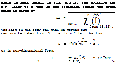 (3.20)
where the plan form area S and the aspect ratio A = 4s /S of the wing have been introduced. Similarly, the drag on the body can be worked out from (3.18), which gives
r8 v fS
5 – ір0 f A<f,(y)vzTrdy = ipovo“^ j Лф<іу
![]() 5 = і l
5 = і l
2 V.
![]() Combining (3.20)and (3.21), we have in non-dimensional form
Combining (3.20)and (3.21), we have in non-dimensional form
![]() s ■
s ■
Thus the vortex drag increases with the square of the lift and falls inversely with the aspect ratio. This is an important relation in wing design, and we shall come back to it many times.
Consider now specifically wings of high aspect ratio at subsonic speeds. Having obtained a solution for the flow in the Trefftz plane behind a wing with a trailing vortex sheet, we can take a next step and determine some properties of the wing itself, especially the flowfield near the wing, which are consistent with the results obtained so far. For this purpose, we consider the special case of a flat wing put at an angle of incidence a to the mainstream direction. Moreover, we assume that the chordwise extent, c, is small compared with its span, 2s, i. e. the aspect ratio of the wing is high:
A » 1. This case may be unnecessarily restrictive with regard to some of the properties we shall derive, but it has the advantage of showing the main concepts and features very clearly.
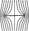
In this case, the downwash is constant over the trace in the Trefftz plane, and the flow in the Trefftz plane is as shown in Fig. 3.2(a). In the absence of the parallel flow, the streamlines of the flow induced by the vorticity distribution along the trace only are shown in Fig. 3.2(b). The downwash vzTr can be related to the overall lift force by (3.20):
In the Trefftz plane, the elemental vortex lines can be regarded as of infi~ nite length fore and aft. On the wing, on the other hand, the spanwise distribution of trailing vorticity is the same as in the Trefftz plane but the elemental vortex lines are of semi-infinite length. Therefore, the induced down – wash is only half that in the Trefftz plane:
 vzW VzTr, J_ о
“i = VQ “ 2 V0 vA L •
Thus the geometric boundary condition on the wing surface is
1 г
«е “ <* " ai “ a – xA L *
where the effective angle of incidence a has been introduced. This is one form of the classical aerofoil equation’, it will be discussed further in Section 4.3.
If the aspect ratio is high, the flow in any plane у = constant may be regarded as twodimensional, as though the wing extended laterally to infinity on either side. This is at best a plausible assumption at this stage, and we shall give a more rigorous derivation in Section 4.3. Here, we may use the solution for the ahordwise distribution of bound vorticity over a twodimensional flat plate at an angle of incidence, which is based on the Kutta – Joukowski theorem (2.46). The chordwise loading is then
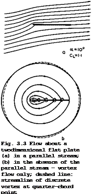 |
where xL and xT are the values at the leading and trailing edges respectively. The corresponding flow has been discussed in connection with Fig. 2.14(a) and is shown in more detail in Fig. 3.3(a). If the parallel stream
is subtracted, the streamlines induced by the bound vorticity alone are as shown in Fig. 3.3(b). Note that the farfield approaches that of an isolated vortex line located at the quarter-chord point of the plate.
We can derive from (3.26) a relation for the sectional, or local, lift coefficient:
 rT
rT
![]() * 1.(x)dx = 2тга = C, . (3.27)
* 1.(x)dx = 2тга = C, . (3.27)
![]() Thus the sectional lift elope CL/ ae “ 2ir. As indicated, may be regarded as constant along the span when A » 1, and thus equal to the overall lift coefficient CT
Thus the sectional lift elope CL/ ae “ 2ir. As indicated, may be regarded as constant along the span when A » 1, and thus equal to the overall lift coefficient CT
(3.28)
which is a very simple relation for the overall lift elope of the wing. This approaches the sectional value from (3.27) as A tends to infinity.
It is consistent with this model of the flow that the resultant air force is normal to the effective flow direction but not to the actual geometric flow direction. Hence the existence of a drag component in the direction of the mainstream. It is instructive to resolve the resultant air force into the components Cjj and Gj normal and tangential to the chordline of the wing according to
![]() CT “ “ = – uCL + Cp
CT “ “ = – uCL + Cp
![]()
 |
Cjj = CL + aCD
which is even simpler than the drag relation (3.22) in that the aspect ratio does not appear (see D Klichemann (1940)). The minus sign is to indicate that the tangential force is directed forward. The question then arises of how such a euotion force can be realised in a practical flow.
In deriving the solution for the chordwise bound vorticity distribution, we have already seen to it that the Kutta condition of smooth outflow from the trailing edge is fulfilled. Now we have to consider what to do with the flow near the leading edge where the load and the velocity are infinite: an infinite pressure over an infinitely small area produces a finite suction force, given by (3.30). Such a corner with a turning of the flow through 180° cannot be negotiated without separation by a viscous incompressible flow, and we have to think of how to modify the shape of the wing in such a way that a viscous flow will remain attached and that the suction force is realised at the same time. This can be achieved by rounding-off the noee of the aerofoil so that a finite suction force acts on a finite forward-facing area. In this way, we arrive at the characteristic shape of the alaeeical aerofoil eection. A typical shape of this kind, together with the velocity distribution along the
|
The Aerodynamic Design of Aircraft
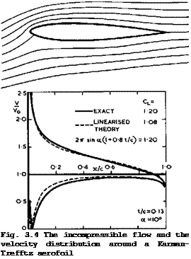 |
surface is shown in Fig.3.4*). Clearly, to negotiate the high turning angle and the subsequent steep adverse pressure gradient is a precarious undertaking for
the air. We also note that, on this particular symmetrical aerofoil, the load is still similar to that over a flat plate: it is far from uniform along the chord and the rear end does not carry much. One would obviously like to design aerofoils which are more heavily and more evenly loaded. We can understand now why the design of suitable aerofoil sections is one of the main problems in the aerodynamic design of this classical type of aircraft. This then is the first major* type of flow we have found, which is suitable for generating lift forces.
Having determined the main characteristic features of the chordwise profile shape, we consider next the question of what the ptanform shape should be, i. e. the spanwise distribution c(y) of the wing chord, which is consistent with the general flow model. We can use the fact here that we already have a solution for the potential difference Дф(у) in the Trefftz plane in (3.19). We now recall that, at the sheet, the tangential velocity component Vy(y) is equal to ±Yt »if Yt is the strength of the vorticity distribution. ^Hence,
*) . . … . This figure shows not only the exact solution for this particular aerofoil
but also an approximate solution according to linearised theory, as discussed
in Section 2.2.
by (3.19). This allows us to link up the vortex distribution in the Trefftz plane with the spanwise load distribution L(y) along the actual wing if we assume that the trailing vortex sheet does not change its shape between the trailing edge of the wing and the Trefftz plane, which is, in any case, implied in the preceding analysis. On the other hand, the shedding of trailing vorticity is related to the change of circulation along the span:
Yt(y) = ^5^- . (3.32)
where
PqVqT = L(y) , (3.33)
which follows from the Kutta-Joukowski theorem (2.46). We can now combine the last three equations and obtain for the spanwise load distribution by integration____
CL(y)c(y) = CL/l – (У/s)2 , (3.34)
that is, the spanwise loading is elliptic, falling to zero at the wing tips like a square root of the distance from the tips. For the flat wing consider here,.and if we want to be equal to the overall value C^, we must
have
c(y) = ff/l – (y/s)2 . (3.35)
This means that the planform is also elliptic.
We now have a consistent flow model, which has given us relations between the overall lift and drag forces and the angle of incidence as well as relations for the chordwise and spanwise load distributions. We also have some guidelines for the shapes of the chordwise aerofoil sections and of the wing plan – form. All these apply to a special case but we shall see later, in Section
4.3, that the departures from this special case are not all that large in practice and that the results derived here give some useful clues to the characteristics of classical unswept wings. The results are the essence of the classical aerofoil theory of F W Lanchester (1915) and L Prandtl (1918).
We digress here to consider briefly a physical interpretation of the drag relation (3.22), which may help us in thinking about these matters. We introduce a fictitious mass flow of air, PqVqS’ , whose rate of change of downward momentum far behind the wing is equal to the lift force on the wing:
L = PoV0S’vzTr. (3.36)
The rate at which kinetic energy is given to such air equals the rate at which work is done in overcoming the vortex drag. Thus
DV0 = iP0V0S’vzTr2 * (3*37)
Pohlhausen has shown that S’ in these equations is the same quantity and that it has the value irs^ for the case that the trailing vortex sheet is plane.
In other words, the mass of air that is accelerated downward to produce the lift is equal to the fictitious mass which flows through a circle round the span of the wing with the mainstream velocity Vq. Elimination of S’ from
(3.36) and (3.37) gives (3.21) and elimination of vzjr gives (3.22). On the other hand, we can draw the important conclusion from (3.36) and (3.37)
that a given value of the actual lift L is generated most efficiently (i. e. with the least drag) if the largest possible mass of air is captured (i. e. if the span is as large as possible) and then subjected to the smallest downward acceleration (i. e. that vzjr is as small as possible). This defines one of the basic problems in aircraft design.
Obviously, there are other, non-aerodynamic, reasons why the span cannot be made arbitrarily large, such as the weight of the structure that would be needed. Thus, as will be discussed in more detail in Section 4.1, aircraft design must strike a balance between all the aspects involved. On the other hand, it will not even be necessary to strive always for the best and for perfection in some or every respect. For example, if a given flight range is to be achieved according to (1.7), and if achievable technological values of the other garameters Hnp and Wp/W are also given, then the aerodynamic parameter L/D (or L/D) needs to reach only a certain value and not the highest possible. Thus the essence of aircraft design is to reach the required values in an economical way without any unnecessary losses.
Returning now to the relations between lift and drag forces, we note that, although we have applied the arguments to special cases, the derivation of the drag equation (3.22) is not so restricted. It holds for wings of any aspect ratio. Further, the relation can be generalised. If we remove first the restriction to straight traces in the Trefftz plane, we can think of other shapes of the trailing vortex sheet which can still produce a constant down- wash in the Trefftz plane. The drag value can then be smaller or greater than that given by (3^22) but we can expect that the functional relationship between Cl and Cjj may still be retained. Thus we can write formally for the vortex drag
s – ivJ * <3-38>
where Kv is a vortex-drag factor which can be greater or smaller than unity. Kv = 1 is then only a convenient standard unit to measure the vortex drag.
We note that only specially designed wings will produce trailing vortex sheets which will move downwardat a constant speed under their own influence. If wings produce vortex sheets with rolled-up cores along the side edges, then these cores themselves cannot have a constant downwash all along the sheet. The vortex drag must then be higher than the corresponding minimum value, i. e.
Kv > 1. Since such rolling-up will happen in all practical cases, it is a
matter of some surprise that there are many cases where the actual drag values lie close to the calculated minimum value. The explanation for this may be that the rolling-up process can be rather slow and without appreciable further energy losses, so-that the flowfield near the wing is still dominated by trailing vortices which are not yet rolled-up to a significant extent. In other words, the Trefftz plane is then effectively closer to the wing rather than at infinity downstream.
Some specific configurations can be treated analytically in a relatively simple manner. These must be shaped in such a way that the trace of the trailing vortex sheet in the Trefftz plane is the same as the shape of the lifting system in a vertical plane through its trailing edge, i. e. the vortex system must produce a constant downwash along the span of the wing and of the trace in the Trefftz plane. All these configurations then have the smallest vortex drag for a given span and overall lift. The problem is every time to find a
![]()
solution for a twodimensional potential flow in the Trefftz plane, where the trace of the trailing vortex sheet is regarded as a solid body in a parallel stream at right angles to it. The method of conformal transformations is usually applied.
The cases which have been treated include biplanes, wings with endplates, with fuselages, with several nacelles, and intersecting wings. A summary of results, together with references to the original work may be found in Sections X.14 and XII.11 of В Thwaites (1960). In many cases, the lift-dependent drag factor of non-planar lifting systems turns out to be smaller than unity, but this does not necessarily mean that such a particular lifting system has a better performance in practice than, say, a simple monoplane wing that produces the same lift. Consider, for example, a wing with endplates of a height h at the wing tips. According to J Weber (1954), the drag factor can be approximated by
![]() 1
1
DL ТГ 1 + h/s 2s/c L.
by (3.38), where c is the mean chord of the wing. This can be rewritten as
which is the same as that of a plane wing of aspect ratio A = 2(s + h)/c.
This means that the vortex drag is about the same whether the span is extended by h on either side or whether endplates of height h are fitted at either wing tip. Thus vertical endplates really pay off aerodynamically in wing design only if they can fulfil another function at the same time, such as serving as fins on a tailplane.
We should also be aware of the fact that any of these lifting surfaces with constant downwash along the span do not give the smallest drag in an absolute sense. For example, if the condition of given span is replaced by another related to achieving the smallest structure weight of the wing, still for a given overall lift, then L Prandtl (1933) has shown that the smallest vortex drag is obtained with a wing planform which is more highly tapered than the ellipse, where the downwash is not constant along the span and the spanwise loading no longer elliptic but falls off more steeply towards the tips. This work has been extended by A Klein & S P Viswanathan (1975) who used more refined assumptions about the structure weight.
All these considerations apply to inviscid flow. Viscous regions can readily be fitted into them on wings with attached flow and near-planar vortex wakes. We can expect that, as a first approximation, a viscous skin-friction drag will manifest itself as a momentum deficit in the Trefftz plane. In the simplest case, we may assume that this will result in a drag term
which is independent of the lift force and additive to the vortex drag from (3.38), so that the overall drag is
![]() S = ^DF + ttA Vl
S = ^DF + ttA Vl
Alternatively, the value of Сцр can be determined directly by integrating the skin-friction forces over the surface of the body. But this cannot be all the drag due to viscous effects. The displacement effect of the boundary layer, discussed in Section 2.4, also leads to a drag force. This may be called a viscous pressure drag. Since the leading term in this effect may be interpreted as an effective reduction Act of the angle of incidence, the associated drag force can be approximated by AaC^ which, in turn is nearly proportional to and could be hidden in the value of Ky in (3.42), al
though it has nothing to do with the vortex drag. It is especially difficult to tell the different drag terms apart in an analysis of experimental results.
(3.42) is widely used as a convenient rough measure of the overall drag of aircraft at subsonic speeds. We recall that the Mach number dropped out in the derivation of the original relation (3.22), although lift and drag by themselves must be expected to be functions of the Mach number. Therefore, the relation for the vortex drag is formally applied throughout the whole Mach-number range, including supersonic speeds.
In practice, it is very important to determine the drag forces accurately so as to be able to make reliable predictions of an aircraft’s performance, not only under cruise conditions but also at low speeds. Here, we must still rely on experiments and, since these are generally done on scaled-down models, the fundamental problem of extrapolating windtunnel results to full scale arises.
To solve this, a practicable technique for measuring and analysing drag is needed. Such a technique can be based on (3.42) if the assumption is accepted that of the two essentially different components – the profile drag Cdf of (3.41) and the vortex drag Cdv of (3.38) – only the first is expected
to exhibit a marked dependence on the Reynolds number and hence a scale effect. This assumption is consistent with the basic flow model we have in mind; it derives from the manner in which we think the presence of the drag force becomes apparent in the surrounding fluid, where two quite different processes are involved: one related directly to energy losses in the fluid entrained into
the boundary layers and wake of the lifting system; the other to the energy required to maintain the large-scale and predominantly inviscid flow generated by the trailing vorticity. It is really only through their connection with these two processes that the drag components can be said to have been defined. This then leads to the question of how each of the two components can be determined separately, preferably by experiment.
It has justifiably been argued by E C Maskell (1972) that the common practice of measuring only the overall drag and then taking the vortex drag to be predictable by the methods of linearised theory cannot be regarded as a serious attempt at an accurate drag analysis; it is especially suspect in high-lift conditions. An approach to be preferred is that of A Betz (1925) who developed a method for the direct determination of the profile drag from measurements in a transverse section of the wake downstream of a lifting wing. The momentum theorem is applied to a control surface bounded upstream and downstream of the wing by transverse planes and, if the flow is assumed to be steady, incompressible, and irrotational, except within the boundary layer and wake of the wing, then the profile drag integrals involve only velocity
components and total heads and have to be evaluated only over the wake. This has recently been refined by E C Maskell (1972) and extended to admit the derivation of a comparable expression for the total drag and its two components. Account is taken also of the constraints imposed on the flow by the presence of the windtunnel walls. This work is still continuing, and further extensions to include compressibility, shockwaves, and time-dependent effects are needed before we have a complete method of drag analysis based on wake measurements.


