A Brief Reference on Wing-in-Ground-Effect Craft
The earliest, albeit unintentional, use of the ground effect in technology is probably due to the Wright brothers whose gliders covered longer distances when flying close to the sands. Later, in 1910, some pilots reported a peculiarly “different feel,” when their aeroplanes flew closer to the ground. This phenomenon, referred to in the literature as a “cushioning effect,” sometimes led to a sudden loss of lift. Nonetheless, the influence of the ground was revealed to be something more than just aerodynamic nuisance after a 56 t Dornier DO-X seaplane increasing its payload and range when flying near
K. V. Rozhdestvensky, Aerodynamics of a Lifting System in Extreme Ground Effect © Springer-Verlag Berlin Heidelberg 2000
the water during its transatlantic service in the early 1930s. It is probable that this evidence triggered a purposeful engineering effort to conceive a craft to take advantage of the ground proximity.
From 1935 a Finnish engineer, Kaario, had been working on a series of his “Aerosledge” vehicles, which were basically a low-aspect-ratio wing mounted on skis. Kaario’s craft showed pitch instability, which was later on recognized as an inherent feature of wing-in-ground-effect vehicles. Following Kaario’s work, many projects of large ground effect machines and real, albeit moderately sized, vehicles appeared; see Belavin [1], Ollila [2], Hooker [3], Rozhdestvensky [4].
The list of projects of large craft includes, for example, Weiland’s “Large Weilandcraft,” “Columbia” of the Vehicle Research Corporation, Boeing’s “Lowboy,” Grumman’s missile ekranoplan, SETOL by McDonnell Douglas, Bertin’s “Signe-14” and others.
Among the moderately sized vehicles built one can name TYoeng’s “Aer – oboat,” Bertelson’s GEMs, Kawasaki К AG series, the Lippisch Aerofoil Boat and their derivative “Airfish” [5, 6], Jorg’s Tandem Flairboats [7, 8], China’s RAM and PAR vehicles [9, 10], Kubo’s /і-Sky Sliders developed with the support of Mitsubishi [11, 12], more recent two-seater vehicles “Hoverwing 2-VT” of Fischer Flugmechanik [13, 14], and “Hydrowing VT-01”of Techno – trans [15, 16].
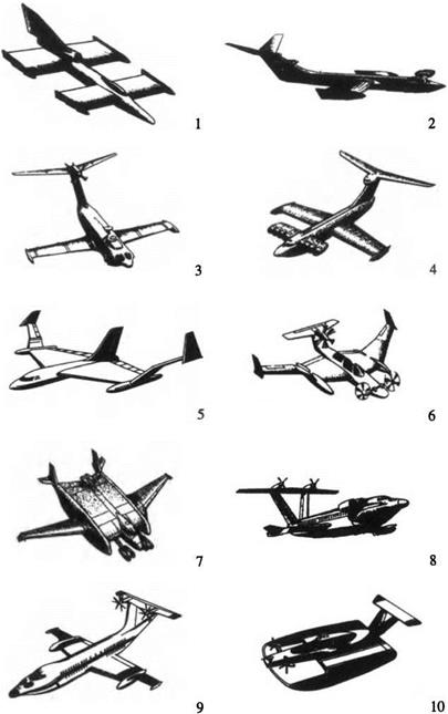
Starting from the 1960s Russia took the world’s lead in creating large ekranoplans, [17]—[21]. This became possible due to the outstanding effort of Rostislav Alexeyev and his famous Hydrofoil Design and Construction Bureau in collaboration with other leading institutions and enterprises. During the following two decades a number of ekranoplans had been built with takeoff weights of 120 through 550 t and a cruise speed in the range of 350-500 km/h. The largest of these was and still is the KM (ship prototype), dubbed in the West, the Caspian Sea Monster. A collection of Russian wing-in-ground-effect vehicles is shown in Fig. 1.1. It reflects the evolution of design concepts and building technology for ekranoplans. Shown in Fig. 1.1 are
• 1 – the tandem scheme borrowed from the hydrofoil design and developed by Alexeyev in the early 1960s.
• the first-generation vehicles, based on an aeroplane type aerodynamic configuration with a fuselage, a highly elevated tail unit, and a power – augmented takeoff feature: 2 – KM, 1967, designed by Alexeyev; 3 – Orly – onok, 1972, designed by Alexeyev and Sokolov [22]; 4 – Loon/Spasatel, 1987, designed by Kirillovykh [20]. One should note that the highly mounted tail surface in the aeroplane scheme is intended to secure (pitch) stability to longitudinal motion.
• the concepts and projects of a new generation of ekranoplans with flying wing and composite wing configurations: 5 – Alexeyev’s flying wing concept (late 1970s); 6 – composite wing configuration (Alexeyev, 1970s); 7 – Bartini’s contact free takeoff (landing) craft with a composite wing aero-
|
Fig. 1.1. A Collection of Russian Ekranoplans in Concepts and Vehicles. |
dynamic scheme [23]; 8 and 9 – Marine Passenger Ekranoplans MPE 400 and MPE 200, designed by Sinitsyn [24].
It should be added that pitch stability for the tailless flying wing configuration 5 can be ensured by special profiling of wing sections and the use of an automatic motion control system. The composite wing scheme (6-9) employs the idea of a functional subdivision of the vehicle’s lifting area into two parts. The central wing of the system enables taking full advantage of power augmentation (blowing under the wing) at takeoff. Side wings add efficiency and, if properly positioned, longitudinal stability in cruising. Further elaboration of the composite wing scheme can be achieved by profiling wing sections, which serves to reduce the tail unit and, consequently, empty weight fraction.
• A smaller vehicle (10; 1996, Sinitsyn) features blowing under the wing (power augmentation) both during takeoff (landing) and cruising. This craft known by the name Amphistar is a six-seater with a cruising speed of 150 km/h [25]. Other examples of the family of unconventional ekranoplans with permanent power augmentation features are Volga-2 and Raketa-2 (project), developed in the Central Hydrofoil Design Bureau named after R. E. Alexeyev.


