A Useful Nozzle Flow Solution
The design of transonic nozzles can benefit from an exact solution of the TSD equation that represents near-sonic flow conditions with a linear acceleration along the plane or axis of symmetry. Consider the two disturbance potential functions:
The reference Mach number has been set to M0 = 1. The first function satisfies the above TSD 4.78 (see also Cole and Cook [7]), whereas the second is a solution of the TSD equation for axisymmetric flow
![]() дф d2ф d2 ф 1 дф
дф d2ф d2 ф 1 дф
– (1 + 1) 2 + 2 + = 0
dx dx 2 дz2 z дz
where z represents the distance from the axis of revolution. These solutions are similar and it will suffice to describe the flow features of one of them. The axisym – metric solution is more relevant to the design of a transonic nozzle for aerospace applications. The perturbation velocity field is given by
|
|
![]()
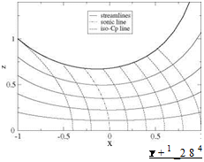
Some remarkable lines are the streamlines and the iso-Cp (or iso-u) lines. The first are obtained by numerical integration of the ODE
![]() dz Y + 1 . (Y + 1)2 3
dz Y + 1 . (Y + 1)2 3
= w = xz + z3
dX 2 16
using a fourth-order Runge-Kutta algorithm. This is an approximation, consistent with the small disturbance tangency condition. It is also possible to introduce a perturbation stream-function that satisfies
![]() дф дф дф y + 1
дф дф дф y + 1
 |
dx = ~pwz = “zdZ ’ dZ = puz = ~—z
![]() , , , Y + 12 (Y + 1) 3 (Y + 1)3 5
, , , Y + 12 (Y + 1) 3 (Y + 1)3 5
ф(х, z) = — X2z – xz3 – z5
2 6 40
Then, the streamlines of the solution can be more accurately obtained by solving Ф=p*a* ^z2 + ф(x, z)) =const. or for planar, 2-D flow Ф=p*a* (z + ф(x, z)) = const. The stream-function can be integrated simultaneously with the potential The Mach number is given by the linear relation
 Y + 1
Y + 1
M (u) = 1 + u
The iso-Cp (or iso-Mach) lines are simply u = const. lines of equation
Y + 1 2
x = u – z2 (4.129)
which are parabolae with axis along the x-axis where the tangent is vertical. The sonic line corresponds to u = 0 and passes through the origin. Note that the sonic line does not correspond to the nozzle throat. One streamline has been selected to represent the nozzle wall (thicker line), Fig. 4.15.
In the supersonic subdomain one can also calculate the characteristic lines. As mentioned, they admit a cusp on the sonic line. Note also that the “line of throats” corresponds to the minimum of each streamline and is given by w = 0, i. e.
Fig. 4.15 Streamlines and iso-Cp lines near a nozzle throat
 (4.130)
The radius of curvature R at the throat is an important design parameter. It varies with the streamline that is used as a nozzle wall and is found to be
Also, the C – characteristic that touches the sonic line on the x-axis is sometimes called the “frontier of transonic flow” because any small perturbation made downstream of it does not affect the incoming flow. This is depicted in Fig. 4.16.
This solution is very accurate near the sonic line since the perturbation is vanishingly small there. It can be used to design a supersonic nozzle producing a uniform flow at Mach number M1. If the Mach number is too large to use the TSD equation, the solution can be matched and continued downstream of the frontier of transonic flow with the full potential equation to achieve an accurate design. For a low supersonic Mach number, say Mi = 1.48, the small disturbance model is acceptable and the calculation can proceed readily as described below.
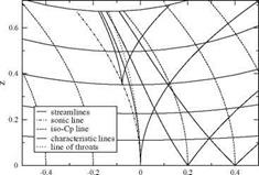 Fig. 4.16 Characteristic lines and line of throats near a nozzle throat
Fig. 4.17 Characteristic initial value problem for a nozzle design providing a uniform flow u = u 1, w = 0
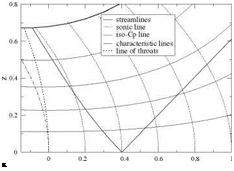 The following initial value problem will provide the design of a uniform supersonic flow. Given M1 the corresponding value of u 1 is determined. With the choice M1 = 1.48 one finds u1 = 0.4. From the point (x1 = u1, 0) one draws the leftrunning C – characteristic along which the potential ф(х, z) as well as (u, v) are known from the exact solution, and the desired right-running straight C+ characteristic line of slope dz/dx = 1 /^J(j + 1)u1 that is bounding the uniform flow region of pertubation velocity (ui, 0) on its right side. On Fig.4.17, these characteristics have been superposed to the analytic solution developed earlier. The potential is also known along the C+ to be, by continuity, ф(х, z) = u1 x – u^/2. In the triangular region between these two characteristics, the characteristic initial value problem is well posed and a solution exists that will replace the analytical solution there. Note that the solution is integrated by marching perpendicular to the flow direction, for example using the method of characteristics.
The design is finalized by integrating the equation for the nozzle wall, starting from the point on the line of throats that provides the desired throat radius of curvature and marching in the flow direction until the C+ characteristic is reached.
Another approach consists in integrating the TSD directly, marching it away from the axis. This will be possible only in the supersonic subdomain. The first step will consist in setting up a Cartesian mesh system (for simplicity) with mesh points Xi = (i – 1)Ax, i = 1, ix, Zj = (j – 1)Az, j = 1, jx with for example Ax = 0.02, ix = 51 and Az = Ax/^J(j + 1)u 1. Initial and boundary conditions are specified on 3 sides of the domain, i. e.
Fig. 4.18 Initial-boundary value problem for a nozzle design providing a uniform flow u = U1, w = 0 and superimposed C+ and C – characteristics
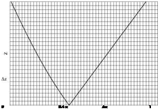 See Fig.4.18.
The numerical scheme is an explicit, second-order accurate, centered scheme for фі, j+1 that reads
In order to initiate the marching procedure, two lines of data are needed. For j = 1 the values of the potential are given by фі,1 = xf /2, 0 < хі < x1 or
U2
фі,1 = u1 xi —2, x1 < xi < 1. The symmetry condition can be implemented simply by accounting for фі,2 = фі,0, where the index 0 corresponds to a fictitious lineat z = – Az, and for the limiting value of 1 фф (x, 0), which leads to the particular form of the scheme that can be solved for фі,2
, , .,фі+1,1 – фі-1,1 фі+1,1 – 2фі,1 + фі-1,1,
-(7 + 1) +
The scheme is explicit and as such must satisfy a stability condition (CFL). However, in contrast to the analysis of transonic flow in a given nozzle, the inverse problem of designing a transonic nozzle is much easier. This is due to the fact that the solution is marched in the direction normal to the flow. Stability is ensured because the most restrictive marching step Az corresponds to the highest value of the axial component of perturbation, here u = u 1, and the choice Az = Ax Д/(7 + 1)u1 is the maximum allowable value for the whole domain, according to the CFL criterion.
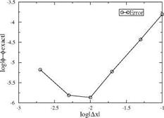
Before solving the design problem, the scheme was used to integrate that particular exact solution of the TSD equation to validate the scheme’s accuracy. The boundary conditions are in this case
Fig. 4.19 Convergence of numerical scheme using exact solution
 ф(0, z) = z4, z > 0
ф(х, 0) = £, w(x, 0) = Щ(x, 0) = 0, 0 < x < 1 (4.135)
. ф(1, z) = 1 + z2 + z4, z > 0
corresponding to x1 = 1. The solution was calculated on several mesh systems with ix = 11, 21, 51 and 101 and compared with the exact solution, using as error norm є = maxi ф(і, jx) – фeXact(i, jx) where zjx = 1. On finer meshes such as ix = 201 or higher, round-off errors were dominating and the convergence test became meaningless. A convergence rate of approximately R = 2.0 was found. This is expected for a second-order accurate centered scheme. A convergence rate of 2.0 was also found for the planar solution. See Fig. 4.19.
The design of a nozzle producing a uniform supersonic flow at Mach number Mi = 1.48, i. e. corresponding to u = 0.4 is shown in Fig. 4.20. The initial-boundary value problem is discretized with a mesh of ix = 51 points. The slope of the C+ characteristic that bounds the uniform flow region is {dx)C + = = 1.02.
Hence Az = 1.02 Ax. The solution is marched 97 steps in z to approximately z = 1. The wall streamline passes through the throat at zthroat = 0.553, which gives the throat a radius of curvature Rthroat = 1.5 and an exit radius z1 = 0.608. The area
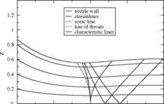 Fig. 4.20 Design of a nozzle providing a uniform flow
U1 = 0.4, w = 0
ratio A1 = Z1 = 1.21, which is 4% larger than the value -4 = 1.16
Athroat Zthroat A
found in isentropic tables. This discrepancy is probably due to the small perturbation assumption, not the two-dimensional effect that places the sonic line in a larger cross section, upstream of the throat.


