Additional Surfaces on Wing
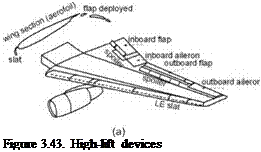
Flaps and slats on a 2D aerofoil are described in Section 3.10. This section describes their installation (Figure 3.43a) on a 3D wing.
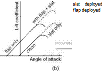
Flaps comprise about two thirds of an inboard wing at the trailing edge and are hinged on the rear spar (positioned at 60 to 66%; the remaining third by the aileron) of the wing chord, which acts as a support. Slats run nearly the full length of the LE. The deployment mechanism of these high-lift devices can be quite complex. The associated lift-characteristic variation with incidence is shown in Figure 3.43b. Slat deployment extends the wing maximum lift, whereas flap deployment offers incremental lift increase at the same incidence.
 |
 |
The aileron acts as the roll-control device and is installed at the extremities of the wing for about a third of the span at the trailing edge, extending beyond the flap. The aileron can be deflected on both sides of the wing to initiate roll on the desired side. In addition, ailerons can have trim surfaces to alleviate pilot loads. A variety of other devices are associated with the wing (e. g., spoiler, vortex generator, and wing fence).
Spoilers (or lift dumpers) (Figure 3.44) are flat plates that can be deployed nearly perpendicular to the airflow over the wing. They are positioned close to the CG (i. e., X-axis) at the MAC to minimize the pitching moment, and they also act as air brakes to decrease the aircraft speed. They can be deployed after touchdown at landing, when they would “spoil” the flow on the upper wing surface, which destroys the lift generated (the U. S. terminology is lift dumper). This increases the ground reaction for more effective use of wheel brakes.
 |
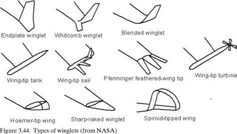
Many types of wing tip devices reduce induced drag by reducing the intensity of the wing tip vortex. Figure 3.44 shows the prevalent type of winglets, which modify the tip vortex to reduce induced drag. At low speed, the extent of drag reduction is minimal and many aircraft do not have a winglet. At higher speeds, it is now recognized that there is some drag reduction no matter how small, and it has begun to appear in many aircraft – even as a styling trademark on some. The Blended
|
|
winglet and Whitcomb types are is seen in high-subsonic aircraft. The Hoerner type and sharp-raked winglet are used in lower-speed aircraft.
The Whitcomb-type wing tip and its variants without the lower extension are popular with high-subsonic turbofan aircraft. Extensive analyses and tests indicate that approximately 1% of induced-drag reduction may be possible with a carefully designed winglet. Until the 1970s and 1980s, the winglet was not prominent in aircraft. In this book, no credit is taken for the use of the winglet. Coursework can incorporate the winglet in project work.
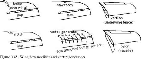
Wing flow modifier devices (Figure 3.45) are intended to improve the flow quality over the wing. In the figure, a fence is positioned at about half the distance of the wingspan. The devices are carefully aligned to prevent airflow that tends to move spanwise (i. e., outward) on swept wings.
Figure 3.45 also shows examples of vortex generators, which are stub wings carefully placed in a row to generate vortex tubes that energize flow at the aft wing. This enables the flow to remain attached; however, additional drag increase due to vortex generators must be tolerated to gain this benefit.
Vortex generators and/or a fence also can be installed on a nacelle to prevent separation.


