Aerofoils – subsonic speeds
So far we have only considered the resistance, or drag, of bodies passing through the air. In the design of aeroplanes it is our aim to reduce such resistance to a minimum. We now come to the equally important problem of how to generate a force to lift or support the weight of an aircraft.
In the conventional aeroplane this is provided by wings, or aerofoils, which are inclined at a small angle to the direction of motion, the necessary forward motion being provided by the thrust of a rotating airscrew, or by some type of jet or rocket propulsion. These aerofoils are usually slightly curved, but in the original attempts to obtain flight on this system flat surfaces were sometimes used.
Lifting surfaces
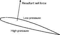
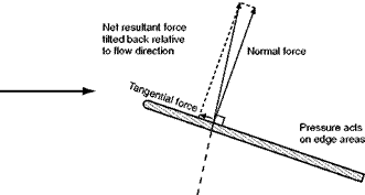
If air flows past an aerofoil, a flat plate or indeed almost any shape that is inclined to the direction of flow, we find that the pressure of air on the top surface is reduced while that underneath is increased (Fig. 3.1, overleaf). This difference in pressure results in a net force on the plate trying to push it both upwards and backwards. In the case of a simple flat plate, you might imagine that the net force would act at right angles to the plate. This is not so, because there is also a tangential force caused by the different pressures that act on the small leading and trailing edge face areas. This tangential force, though small, is by no means negligible. Rather surprisingly, the pressure at the leading edge is normally very low, and at small angles of inclination, the tangential force will act in the direction shown in Fig. 3.2 (overleaf). The reasons for the low pressure at the leading edge will be shown later. Note, that although the tangential force may be directed towards the front of the plate, the resultant of the tangential and normal forces must always be tilted back relative to the local flow direction.
Direction of airflow

 |
|
Fig 3.1 Resultant force on an aerofoil due to pressure difference
Fig 3.2 Forces due to pressure differences in a flat plate
Lift and drag
The resultant or net force on the lifting surface may be conveniently split into two components relative to the airflow direction as follows –
1. The component at right angles to the direction of the airflow, called LIFT (Fig. 3.3).
2. The component parallel to the direction of the airflow, called DRAG (Fig. 3.3)
The use of the term ‘lift’ is apt to be misleading, for under certain conditions of flight, such as a vertical nose dive, it may act horizontally, and cases may even arise where it acts vertically downwards.
Airflow and pressure over aerofoil
It was soon discovered that a much greater lift, especially when compared with the drag, could be produced by using a curved surface instead of a flat one,
|
|
Fig 3.3 Lift and drags shown for the case of a descending aircraft
and thus the modem aerofoil was evolved. The curved surface had the additional advantage that it provided a certain amount of thickness, which was necessary for structural strength.
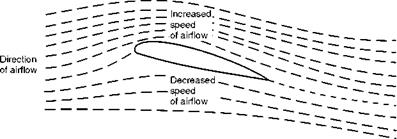
Experiments have shown that air flows over an aerofoil (Fig. 3.4) much more smoothly than over a flat plate.
In Fig. 3.4, which shows the flow of air over a typical aerofoil, the following results should be noticed –
1. There is a slight upflow before reaching the aerofoil.
2. There is a downflow after passing the aerofoil. This downflow should not be confused with the downwash produced by the trailing vortices as described later.
3. The air does not strike the aerofoil cleanly on the nose, but actually divides at a point just behind it on the underside.
4. The streamlines are closer together above the aerofoil where the pressure is decreased.
This last fact is at first puzzling, because, as in the venturi tube, it may lead us to think that the air above the aerofoil is compressed, and that therefore we should expect an increased pressure. The explanation is that the air over the
|
|
Fig 3.4 Airflow over an aerofoil inclined at a small angle top surface acts as though it were passing through a kind of bottleneck, similar to a venturi tube, and that therefore its velocity must increase at the narrower portions, i. e. at the highest points of the curved aerofoil.
The increase in kinetic energy due to the increase in velocity is accompanied by a corresponding decrease in static pressure. This is, in fact, an excellent example of Bernoulli’s Theorem.
Another way of looking at it is to consider the curvature of the streamlines. In order that any particular particle of air may be deflected on this curved path, a force must act upon it towards the centre of the curve, so it follows that the pressure on the outside of the particle must be greater than that on the inside; in other words, the pressure decreases as we move down towards the top surface of the aerofoil. This point of view is interesting because it emphasises the importance of curving the streamlines.


