Canard Configuration
Canard is French for “goose,” which in flight stretches out its long neck with its bulbous head in front. When a horizontal surface is placed in front of the aircraft, it presents a similar configuration; hence, this surface is sometimes called a canard.
The Wright Brothers’ Flyer had a control surface at the front (with a destabilizing effect), which resulted in a sensitive control surface. Military aircraft use a canard to enhance pitch control. However, the use of a canard in civil aircraft applications serves a different purpose (Figure 3.48).
In general, the inherent nose-down moment (unless a reflex trailing edge is employed) of a wing requires a downward force by the H-tail to maintain level flight. This is known as trimming force, which contributes to trim drag. For an extreme CG shift (which can happen as fuel is consumed), high trim drag can exist in a large portion of the cruise sector. The incorporation of a canard surface can reduce trim drag as well as the H-tail area, SH. However, it adds to the manufacturing cost and, until recently, the benefit from the canard application in large transport aircraft has not been marketable.
Many small civil aircraft have a canard design (e. g., Rutan designs). A successful Bizjet design is the Piaggio P180 Avanti shown in Figure 3.48. It has achieved a very high speed for its class of aircraft through careful design considerations embracing not only superior aerodynamics but also the use of composite materials to reduce weight.
|
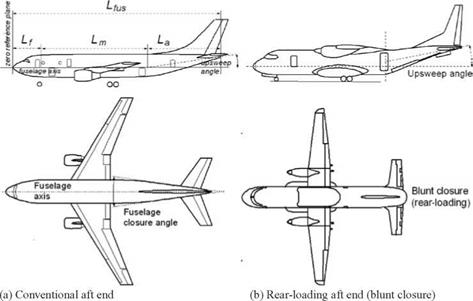
Figure 3.49. Fuselage geometrical parameters: lengths associated with the fuselage |
Canard Volume Coefficient, CCt
This also is derived from the pitching-moment equation for steady-state (i. e., equilibrium) level flight. The canard reference area, SC, has the same logic for its definition as that of the H-tail. Its tail arm is LCT. The canard reference area is given as:
Sct = (Cct)(Sw x MAC)/Lct, (3.48)
where CCT is the H-tail volume coefficient, 0.5 < CHT < 1.2; a good value is 0.6 to 0.9, depending on whether it is a conventional H-tail. The LCT is the H-tail arm = distance between the aircraft CG to the ac of MACCT. In general, SCT/SW & 0.2 to 0.3.


