Equation of Motion for a Flapping Blade
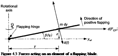
In hovering flight, the solution for f$ is a constant (= fio) independent of Jr and this angle is called the coning angle. Under forward flight conditions as a result of the cyclically (azimuthally) varying airloads, the blade flaps up and down in a periodic manner with respect to azimuth. Consider Fig. 4,5, which shows the line of action of the aerodynamic forces, the centrifugal forces, and the inertial forces acting on a small element of the blade span. Define the moment to be positive in a direction such as to reduce /3. The centrifugal moment about the hinge is
|
d{McF) = (mdy)y2Q2fi = my2Q,2dy. |
(4.24) |
|
The inertial moment about the hinge is |
|
|
d(I) — (mdy)y2$ = my2$ dy |
(4.25) |
|
and the aerodynamic moment about the hinge is |
|
|
d(Mp) = – Ly dy, |
(4.26) |
where the sign of the latter term is noted. It will be assumed that there is no hinge offset, that is, e = 0. Therefore, the equation of motion can be derived by summing the moments about the flap hinge giving
nR pR pR
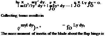
/ d(McF) + / d{l) + / d(Mp) = 0. (4.27)
Jo Jo Jo
 |
Ldy
 |
|
Introducing the relevant expressions for d(McF), d(I), and d(Mp) gives
Thus the equation of flapping motion in Eq. 4.29 can be written as
![]() fR
fR
Ib’P + IbQ1P = / Lydy.
Jo
 |
|
Noting that fr = Qt results in the following transformations
or in short-hand notation simply as
![]() P + P = TT77 f Ly dy
P + P = TT77 f Ly dy
Now, consider the aerodynamic forces. At any blade element of chord c at a radial distance у from the rotational axis it can be readily shown using the blade element theory (Section 3.5) that with uniform inflow the aerodynamic force per unit length is
![]()
 |
||
L = рЩсС, = dVcC., (в – g – £) so the aerodynamic moment about the hinge will be
The Lock number is defined as
![]()
![]() pCiacR4
pCiacR4
h
which can be viewed as a measure of the ratio of aerodynamic forces to inertial forces. For a typical helicopter rotor, the value of the Lock number varies from 5 to 10. Notice, however, that its value depends on the density of the air and so will be affected by changes
in density altitude (see Section 5.2). The equation governing the behavior of the flapping blade becomes
![]() P + P
P + P
which on rearrangement gives
This is the flapping equation for a centrally hinged blade, that is, one that is hinged at the rotational axis with e = 0. A more general form is to leave the aerodynamic force (moment) on the right-hand side unintegrated, in which case
![]() P + fi = yMp,
P + fi = yMp,
where
Notice the similarity of Eq. 4.40 with the equation of motion of a single degree-of – freedom spring-mass-damper system, that is, m’x + cx + kx — F, where x is the displacement, m is the mass, c is the damping, and к is the spring stiffness. This system has an undamped natural frequency of con = sjkjm. Therefore, by analogy with Eq. 4.40 the undamped natural frequency of the flapping blade about a hinge located at the rotational axis is once per revolution (1/rev) or wn — £2 rad/s.
Consider first the case where the rotor operates in a vacuum, in which case there are no aerodynamic forces present. The flapping equation reduces to
![]()
![]() fi+fi = o.
fi+fi = o.
It is easy to show that this equation has the general solution
fi = fic COS j/ + fiis sin т/f,
where fic and fis are arbitrary coefficients. Thus, in the absence of aerodynamic forces, the rotor takes up an arbitrary orientation in inertial space. In effect, the rotor acts like a gyroscope. The introduction of aerodynamic forces produces an aerodynamic flapping moment about the hinge, which causes the rotor to precess to a new orientation until the aerodynamic damping (which is contained inside the Mp term) causes equilibrium to be obtained once again.
In forward flight, the aerodynamic forces provide the forcing to the flapping blade at multiples of the rotor frequency. This aerodynamic excitation is primarily at 1/rev. The blade flapping motion with respect to the rotor hub can be represented as an infinite Fourier series of the form
p([r) = fio + file COS ir + fils sin f + fi2c COS 2f + fi2s sin 2f л
CO
![]() = Po+^2 (ft™cos n^+p™ sin n^ ’
= Po+^2 (ft™cos n^+p™ sin n^ ’
/2-І
 |
where the time scale has been nondimensionalized with respect to rotor time such that the dimensionless period is 2n radians. The Fourier coefficients may be evaluated from the flapping displacements using
|
2 n |
pin |
|
|
/ P dJf, Jo |
(4.45) |
|
|
fine = — T. |
p2n |
|
|
I P cos пф dф, Jo |
(4.46) |
|
pciacR4Q2 = 4′ 2 Ja |
Assuming uniform inflow and linearly twisted hlades, we can evaluate the aerodynamic flapping moment about the hinge analytically using the blade element theory where

+ 0tw ( 77: + ~r sin Ф + ~r sin2 1If 10 4 6
and this result can then be substituted into Eq. 4.40 to compute fi.
Some interesting characteristics of the resulting flapping equation are as follows:
1. In forward flight, that is, when p ф 0, the equation has periodic coefficients. This does not allow an analytical closed-form solution of the flapping equation.
2. The flap damping term, which is the coefficient associated with the ft term in Eq. 4.50 for Mp, is
Y ( 4 .
— I 1 4- —11 cin tlr I
s Vі ‘ з—;’
which is of aerodynamic origin (all the terms multiplied by the Lock number у come from the aerodynamics) and is usually very high. For the case of hover and for the natural frequency of 1/rev, the corresponding damping ratio is у j 16. For a Lock number у = 8 this means that the damping is 50% of the critical value; thus the blade flapping motion is stable and well damped.
3. Finally, notice that the flapping equation has been derived with respect to the plane defined by the hub of the rotor, and so both the flap angle fi and the pitch control angle в will generally be functions of the azimuth angle ф.
The general flapping equation of motion cannot be solved analytically in closed form for the general case of p, ф 0. Therefore, two options present themselves:
![]()
![]() Solve the equation numerically. The equation can be integrated for given values of collective pitch 6q, lateral cyclic 6c, longitudinal cyclic 6s, and inflow A,. The selection of the initial conditions for the flapping is not very important because even extreme initial conditions will simply cause a numerical transient that will disappear after a few numerical iterations because of the high damping present in the blade flapping motion. The main problem with the numerical solution is that
Solve the equation numerically. The equation can be integrated for given values of collective pitch 6q, lateral cyclic 6c, longitudinal cyclic 6s, and inflow A,. The selection of the initial conditions for the flapping is not very important because even extreme initial conditions will simply cause a numerical transient that will disappear after a few numerical iterations because of the high damping present in the blade flapping motion. The main problem with the numerical solution is that
the various rotor geometry parameters and operational flight conditions.
Find a periodic solution. In this case the problem is to find a steady-state, periodic solution, in the form of a Fourier series. Obviously this solution is not adequate for transient situations such as during a maneuver, but it allows the identification of the relationships between the flapping response and the various problem parameters.
Assuming the solution for the blade flapping motion to be given by the first harmonics only, that is,
P(f) = Po + file cos if/ + Pu sin if (4.51)
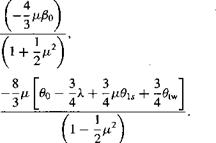
and harmonically matching constant and periodic (sine and cosine) terms on both sides of the derived flapping equation gives
![]()
![]()
![]()


 (4.53)
(4.54)
are obtained:
Pis – Oic = 0 or /8i,= 0ic, (4.55)
Pic + 0b = 0 or Pic = -0i,. (4.56)
This shows that there is an equivalence between pitching motion and flapping motion. If the cyclic pitch motion is assumed to be
в = Oq + віє cos if/ + 01, sin if/, (4.57)
then the flapping response will be
P = Po + віє sin if/ — 0i, cos if/ (4.58)
= Po + 0ic cos (if/ – ^ J + 0i, sin [f – . (4.59)
Therefore, because of the dynamic behavior of the blade, the flapping response lags the blade pitch (aerodynamic) inputs by тс/2 or 90°, which is a resonant condition1 and is independent of any damping. Also, notice the one-to-one correspondence between a unit of pitch and a unit of flapping. This means that when the pilot inputs a unit of cyclic pitch, the rotor will respond with a unit of flapping. Strictly speaking this behavior is for a rotor with a flapping hinge at the rotational axis, but even with a hinge offset the underlying physics and rotor response is essentially similar. The effect of a hinge offset on the flapping problem will be considered in Section 4.7.


