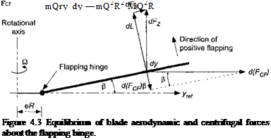
Equilibrium about the Flapping Hinge
Consider now the mathematical analysis of a rotating flapping blade. Figure 4.3 shows a rigid (aeroelastically stiff) rotor blade flapping about a hinge located at a distance eR from the rotational axis. The equilibrium position of the blade is determined by the balance of aerodynamic and centrifugal forces (CF). The contributions from the gravitational forces on the blade are small relative to the other forces and can be neglected. Furthermore, because the centrifugal forces are much larger than the aerodynamic forces, the flapping (coning) angle p is usually quite small (between 3° and 6° is typical for a helicopter rotor).
Assume first for simplicity that the flapping hinge is at the rotational axis, that is, e = 0. For other than teetering rotor designs (see Section 4.13.1), the flapping hinge is always offset a small distance from the rotational axis, but this does not alter the fundamental physics of the blade dynamics problem. The rotational speed about the axis is Q radians per second and is constant. Assume a uniform mass per unit length of the blade, m. Consider a small element of the blade of length dy. The mass of this element is mdy. The forces on the element are aerodynamic and centrifugal. The contribution of this small element to the centrifugal force acting in a direction parallel to the plane of rotation is
![]() cI(Fcf) = (mdy)yQ2 = mQ2y dy.
cI(Fcf) = (mdy)yQ2 = mQ2y dy.
К
 |
|
Therefore, the total centrifugal force acting on the blade is
where the mass of the uniform blade is M (= mR). Notice that the centrifugal forces increase linearly in proportion to blade mass and length and are also proportional to S32. If the blade is coned up at some angle ft, then the contribution of this small element to the CF acting in a direction perpendicular to the blade is
d(FcF) sin ft = (mdy)yQ,2 sin ft ту іl2 ft dy. (4.3)
The moment about the flapping hinge (at the rotational axis) as a result of the centrifugal forces produced by all the elements is, therefore,
The aerodynamic moment about the flap hinge, Mp, depends on the distribution of lift, L, across the blade, that is,
Mp — — f Ly dy. (4.5)
Notice that the negative sign indicates that the aerodynamic moment is in the opposite direction to the centrifugal moment. The rotating blade will reach an equilibrium position where the CF moment about the hinge is equal and opposite to the aerodynamic moment about the hinge. Therefore, the equilibrium equation can be written as
![]()
![]() Mp + Mqf — 0
Mp + Mqf — 0
and so the equilibrium or coning angle fto will be given by 3 f Lydy
о JO_____
P0 MQ2R2 ‘
This result is valid for any form of the aerodynamic loading over the blade. Also, the flapping hinge has been assumed to lie at the rotational axis of the rotor. For a parabolic distribution
of loading of lift over the blade (no blade twist), the center of lift will be located at 3/4 blade radius so that
![]() 3
3
— R x blade lift.
4
A rotor with ideal twist and uniform inflow will produce a linear (triangular) lift loading, which has a center of lift located at 2/3 blade radius, that is,
Therefore, it is clear that this latter case will produce a smaller aerodynamic moment about the hinge for the same total blade lift. For the case where the blade lift is distributed in a triangular manner across the blade (ideal twist) the coning angle /Зо is determined from
2 ![]() 2
2
-R x blade lift——- R Fcf P — 0
З.3й
or in general for given lift distribution
The important point to remember is that the coning angle increases in proportion to rotor thrust and decreases inversely with centrifugal forces. In other words, increasing either blade mass or rotor speed will decrease the coning angle.
In practice the flapping hinge is not normally at the rotational axis (except for teetering rotors) but is offset by a small distance, e R. Typically, e < 0.15. In this case, the aerodynamic moment about the flap hinge, Mp, is
Мр = – f Ly dy. (4.12)
JeR
Also, the CF moment about the hinge is
 |
||
where M — mR( 1-е). Therefore, in this case the coning angle will be given by


