Example: Plunging Plate
This classical test case represents a flat plate aligned with the incoming flow that is accelerated impulsively to a uniform velocity W < 0 parallel to the z-axis, | W | ^ 1. This is equivalent to setting the plate abruptly at incidence a = —W, which is the option implemented here. Although the incidence a is expected to be small in absolute value, it is possible to set it arbitrarily to the value a = 1 rad since the problem is fully linear. For any small value of incidence, the solution obtained needs to be multiplied by a. This problem has been solved numerically and the solution Г(х, t) has been compared with the numerical evaluation of the integral equation that corresponds to the solution past a thin airfoil. The integral equation reads, see JJC [1]:
![]() ™ , d fl+t Г(1 +1 — t)(£ + Vt(t — 1))dt na = 1 (t) + — —
™ , d fl+t Г(1 +1 — t)(£ + Vt(t — 1))dt na = 1 (t) + — —
dtj 1 ^£(£ — 1)(2£ — 1 + 2^t(£ — 1))
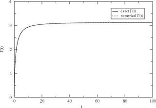
Here r(t) represents the total bound circulation Г(с, t) formulated with dimensionless variables or equivalently setting U = c = 1. The tangency condition is treated as indicated in Chap. 3, in the case of steady flow, but accounting now for the induced velocity contribution of the shed vortices. The results for the circulation are shown in Fig. 5.4 for At = 0.01.
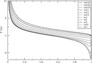
The vorticity distribution on the flat plate is displayed in Fig. 5.5. The initial low value of circulation is obtained with an almost perfectly anti symmetrical distribution of vorticity, except for the Kutta-Joukowsky condition which breaks the symmetry. The initial pressure distribution is very different from that at steady-state and the use of a steady profile polar to study unsteady flow (quasi-steady approach) would not give a realistic representation of the pressure nor of the pitching moment at the same lift in this rapidly changing flow.
|
Fig. 5.4 Comparison of circulation r(t) obtained with thin airfoil theory and integral equation, a = 1 rad |
|
x Fig. 5.5 Time evolution of the vorticity distribution on the plate, a = 1 rad |
One notable feature of the method is the scheme and the mesh for solving the convection equation along the vortex sheet. The exact solution to the convection of vorticity is
Г(х, t) = F(x — Ut), x > c, x — Ut < c (5.35)
where F is a function of a single argument £ = x — Ut, that satisfies F(c — Ut) =
Г(с, t)
hence the exact solution is
x — c
Г(х, t) = Г c, t – , x > c, x – Ut < c (5.36)
This represents a time shift without distortion of the trailing edge circulation along the x-axis. It is possible numerically to achieve the same result with a scheme that has the “perfect shift” property. This is the case with a two-point scheme, at Courant-Friedrich-Lewy (CFL) number one
U At
CFL = = 1 (5.37)
Ax
![]()
![]()
 |
|
and with parameter в set to в = 2. A uniform mesh is constructed with Ax = UAt to the far field point, say x = 100c. The scheme reads
This is a combined implicit/explicit scheme, which reduces to Crank-Nicolson scheme for в = 1 and is unconditionally stable for в > 2. The upper index n represents the time step and v is the inner iteration counter used to converge the circulation so that the tangency condition on the plate as well as the convection equation in the wake are satisfied to a prescribed accuracy at time tn+1.
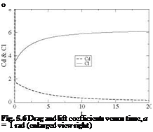
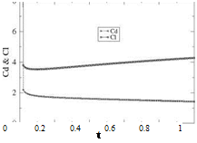
Results for the lift and drag coefficients are shown in Fig. 5.6.
 |
 |
The lift and drag coefficients tend to infinity near t = 0. Numerically, the common value at the first time step t = At is of order A, specifically, with At = 0.01 one
Fig. 5.7 Circulation and vorticity at time t = At
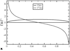 finds Ci = 160.5 and Cd = 158.9. Then drag decreases monotonically to zero as steady-state is approached, whereas lift decreases then increases to its final value of n. If the term D’2 had been included, the result for drag would have been Cd (t) = Cl (t) since w(x, 0, t) = —Ua =—U and (xQ — x)da + d = 0. Enlarging the scale near t = 0 provides a better look at the early evolution of those coefficients, Fig. 5.6. One can see from the numerical results that, at the first time step, the suction force is not present, but with the second time step the suction force already cancels half of the drag.
It is also possible to look at the circulation and vorticity distributions at t = At, Fig. 5.7. It is clear that at a very early time t = є > 0, the circulation must be elliptic since this gives a constant w(x, є) = a.


