H-Tail
The H-tail consists of the stabilizer (fixed or moving) and the elevator (moving) for handling the pitch degree of freedom (Figure 3.46a). The H-tail can be positioned low through the fuselage, in the middle cutting through the V-tail, or at the top of the V-tail to form a T-tail (see Figure 3.33).
Military aircraft can have all moving H-tails with emergency splitting in case there is failure, and there are several choices for positioning it (see Chapter 4). Figure 3.46a shows the geometrical definition of conventional-type H-tail surfaces. Like the wing planform definition, the H-tail reference area, SH, is the planform area including the portion buried inside the fuselage or V-tail for a low – or mid-tail location, respectively. The T-tail position at the top has a fully exposed planform.
|
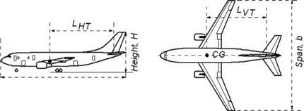
Figure 3.47. Geometric parameters for the tail volume coefficients |
3.22.1 V-Tail
The V-tail consists of a fin (fixed) and a rudder (moving) to control the roll and yaw degrees of freedom (see Figure 3.46). The figure shows the geometrical definition of a conventional-type V-tail surface reference area, SV. The projected trape – zoidal/rectangular area of the V-tail up to this line is considered the reference area, SV. Depending on the closure angle of the aft fuselage, the root end of the V-tail is fixed arbitrarily through a line drawn parallel to the fuselage centerline, passing through the point where the midchord of the V-tail intersects the line.


