Inflow Model of Mangier & Squire
Another inflow model that has found some use in rotor analyses is that developed by Mangier (1948), Squire (1948), and Mangier & Squire (1950). The method uses the incompressible, linearized, Euler equations to relate the pressure field across the disk to an inflow. The solutions conveniently satisfy Laplace’s equation, so that the effects of different forms of loading can be combined by superposition. This theory is partially summarized by Bramwell (1976) and Stepniewski & Keys (1984). Mangier & Squire assume that the loading on the rotor disk can be expressed as a linear combination of two fundamental forms: Type-1, which is an elliptical loading, and Type-3, which is a loading that vanishes at the edges and center of the disk. The pressure loading can be written as
with r being the distance from the rotational axis. These two pressure distributions correspond to extreme forms of the disk loading, which in the real case will typically comprise a
For Type-1 disk loading, the inflow is exactly linear for a = 0 and is only a weak function of a. Type-3 disk loading gives a more nonuniform distribution of inflow, with zero at the center of the disk. Both forms of the assumed disk loading give a lateral distribution of inflow that is symmetric with respect to the longitudinal axis of the rotor. Bramwell (1976) uses Glauert’s high-speed approximation to the inflow and replaces the leading 2Cr//x term in Eq. 3.181 by 4A0, where A.0 is the mean inflow from momentum theory. This implies that the Mangier & Squire theory is valid through hover, but clearly it is not because it violates the high-speed assumptions made in the original work that u, « V^. Therefore, the theory should be used only for advance ratios greater than about 0.1.
When applying Mangier & Squire’s theory, it can be assumed that the loading on the rotor is described by a linear combination of the Type-1 and Type-3 loadings, that is,
Ap = w^Api + ісзДрз, w i+i(;2=l – (3.188)
This is the main disadvantage of theory, which requires the aerodynamic loading on the rotor to be known or assumed a priori. Based on downwash measurements behind a rotor, Fail & Eyre (1954) show that the downwash behind the advancing side of the rotor corresponds to Type-1 loading, whereas from behind the retreating blade the downwash corresponds closely to Type-3 loading. It would seem, however, that at high rotor advance ratios, say greater than 0.5, the onset of reverse flow and retreating blade stall begin to invalidate these loading assumptions – see Ormiston (2004).
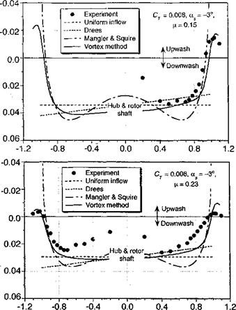
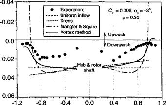
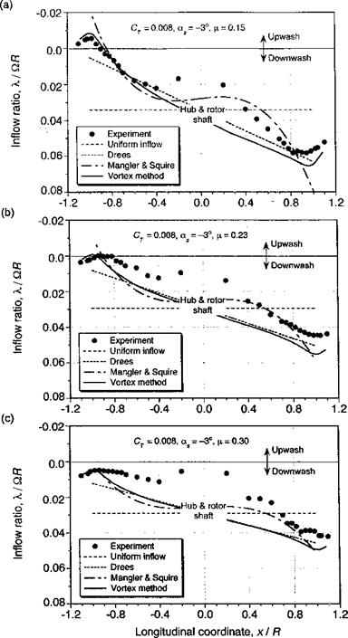
The results from the various inflow models described above are compared with inflow measurements over the rotor disk in Fig. 3.29. These data are taken from Elliott et al. (1988), which were measured one chord above the rotor plane using a LDV system. Because this experiment used both a rotor and a fuselage, the measured results cannot be considered entirely representative of an isolated rotor. The rotor was trimmed such that the TPP was perpendicular to the rotor shaft, with a forward shaft tilt, of —3° (disk AoA of 3°). Figure 3.29 shows that the inflow along the longitudinal axis of the rotor is reasonably well described by linear inflow models such as that of Drees, or with the Type-1 loading in the Mangier & Squire model. The main discrepancies are at the leading and trailing edges of the disk, and also near the rotor hub.
Using a simple average of Type-1 and Type-3 loadings (w = шз = 0.5), Mangier & Squire’s theory gives a somewhat better description of the longitudinal inflow, especially over the back of the rotor. Strictly speaking the coefficients of the Mangier & Squire theory are obtained by solving for the rotor loading (Ap) at the given trim state by means of the BET. Vortex theory (described in Section 10.7) does much better at the leading and trailing edges of the disk and agrees with the linear inflow model over the remainder of the disk. The somewhat larger discrepancies found between all of the theories and the measurements with increasing advance ratio are almost certainly a result of perturbations to the velocity field caused by the rotor hub and also the fuselage below the rotor. Because the mean rotor inflow decreases slightly with increasing advance ratio and the fuselage perturbations increase, the net effect is that a larger fraction of the total inflow is affected by the presence of the fuselage (see Section 11.2.1). Such effects are not easy to calculate but at least must be carefully recognized as a contributing factor to most rotor inflow measurements. The lateral distribution of inflow across the disk is found to be relatively uniform compared to the longitudinal variation but decreases rapidly near the edges of the disk. Outside the edges of the disk, there is an upwash velocity. Drees’s model is not unrealistic, but Mangier & Squire ’s theory gives a much better description of the inflow near the edges of the disk and agrees closely with the results from vortex theory. Again, the influence of the fuselage and rotor hub are responsible for some of the discrepancies seen between theory and experiment.
![]()
|
|
|
|
|
|
|
|
|
|
|
|
|
|
|
|


Lateral coordinate, yl R
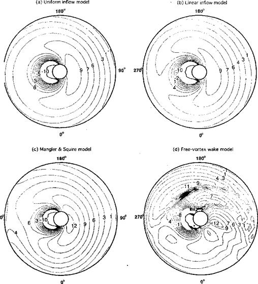
Examples of the predicted Ao A over the rotor disk in forward flight are shown in Fig. 3.30 using four levels of inflow modeling, ranging from uniform inflow to a free-vortex wake prediction (see Chapter 10). In all cases, the rotor was trimmed (see Section 4.14) to meet the same thrust requirement and to ensure that the rotor tip path plane was at the same orientation. Notice in each case the highly nonuniform AoA over the rotor disk. While there are some differences in the AoA distribution when going from a uniform to a linear inflow model, it is the Mangier & Squire model that first begins to pick up the larger nonuniformities in AoA on the retreating side of the disk. Even here, however, the differences are not large
|
Figure 3.30 Predictions of the AoA over the rotor disk in forward flight using four levels of inflow modeling, (a) Uniform inflow model, (b) Linear inflow model, (c) Mangier & Squire inflow model, (d) Free-vortex wake model. CT = 0.008, д = 0.25, as = 8°. Calculations courtesy of Shreyas Ananthan. |
compared to linear inflow assumptions. The reverse flow region (see Fig. 5.9) is evident here. The free-vortex model resolves the individual tip vortices in the wake, which in this case appear as ridges of tightly packed AoA contours in the second and third quadrants of the disk (see later in Fig. 10.13). It is here that the fidelity of vortex wake models start to come into their own for blade airloads predictions, despite their much higher computational cost.
Ormiston (1972) describes a more general inflow formulation in the spirit of Mangier & Squire’s approach, where the rotor loading and inflow are solved more consistently. For a simple uniform bound circulation distribution on the blades, the inflow results appear substantially similar to those obtained with Mangier & Squire’s theory. See also Ormiston (2004). Other more recent developments of the actuator disk inflow model are described by Peters et al. (1987) and Peters & He (1989, 1995). In this theory, the acceleration potential and inflow distribution are expressed in the form of an infinite series of shape functions. When these are substituted into the incompressible, linearized Euler equations, a set of first-order ordinary differential equations are obtained. An aerodynamic loading model is required to solve the equations, which is based on a standard blade element approach. These more recent inflow methods are still in a state of ongoing development (see Section 10.9) but have been shown to give improvements in predictive capability for many rotor problems, especially those involving rotor aeroelasticity. An advantage is that they avoid the need to explicitly model the complicated nature of the true vortex wake and so are computationally less demanding than say, methods based on vortex theory.


