Longitudinal Flapping Angle
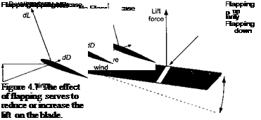
The coefficient 0lc represents the amplitude of the pure cosine flapping motion (Fig. 4.6). This represents a longitudinal or fore aft tilt of the rotor tip path plane. In forward flight, the rotor disk has a natural tendency to tilt back (longitudinally) because of the dissymmetry in lift produced between the advancing and retreating sides of the disk. As a result of the higher dynamic pressure on the advancing side of the disk, the blade lift is increased over that obtained at if = 0° and j/ = 180°. Therefore, as the blade rotates into the advancing side of the disk, the excess lift causes the blade to flap upward, which decreases its lift. This behavior is shown more clearly in Fig. 4.7.
For a single degree-of-freedom linear, time-invariant system excited at its natural frequency, there will always be a phase lag of 90° between the input and the output.
Over the front of the disk the dynamic pressure reduces progressively and the blade reaches a maximum displacement with /3 = 0 at i/r = 180°. As the blade rotates into the retreating side of the rotor disk, the deficiency in dynamic pressure causes the blade to flap downward. This downward flapping motion increases the AoA at the blade element, which tends to increase blade lift over the lift that would have been obtained without flapping motion. This upward and downward flapping of the blade tends to reduce and increase the AoA at the blade elements by an amount
![]()
![]()

Aa(y, p) = — tan-1 (——– ——— ) = — tan-
 |
Qy + pQRj
For example, as a result of the flapping upward ф > 0), the blade lift tends to decrease relative to the lift that would have been produced without a flapping hinge. Conversely, for flapping downward, the blade lift tends to increase relative to the lift that would be produced without the flapping hinge.
The upshot of all this flapping motion is that the rotor blades reach an equilibrium condition again when the local changes in AoA and aerodynamic loads as a result of blade flapping become sufficient to compensate for local changes in the airloads resulting from variations in dynamic pressure between the advancing and retreating sides of the disk. For the situation described previously, in the final equilibrium condition the disk will be tilted back longitudinally with respect to the hub (i. e., a —fc flapping motion). Remember that the forcing function in this case is phased such that the maximum aerodynamic force occurs at fr = 90°, but because of the dynamic behavior of the rotor blade, the maximum flapping displacement occurs ж/2 or 90° later at if/ = 180°. This is of fundamental importance because it allows an understanding of what happens to the rotor flapping under the action of aerodynamic loads that are phased differently with respect to the rotor azimuth.


