Murman-Cole Scheme
Murman and Cole introduced in 1970 a “type-dependent” scheme and a line relaxation algorithm to solve the TSD equation. It was the first time that such a scheme was employed, in which different discretizations are used at subsonic points (centered) and supersonic points (upwind). Although they started from the conservative form of the PDE (Eq. 4.78), the first scheme did not conserve mass across a shock wave, resulting in jump conditions not being satisfied. The reason was that in the switching back of the scheme from an upwind – to a centered-scheme, a loss of conservation occurred. This was later corrected by Murman with a fully conservative four-operator scheme [3]. The sonic-point operator of Murman was revisited by Chattot [4] along with extension of the scheme to the solution of the equations of gas dynamics, a system of three first order PDEs. The four-operator scheme with the modified sonic point treatment is presented here. Lets assume for simplicity that the solution is sought on a Cartesian mesh system with uniform mesh steps Ax and Az. In this type-dependent scheme, one defines the local flow regime by comparing the x-component of the perturbation Ui, j with the sonic perturbation u *, where the “switches” are defined as
and the most recent values of the potential ф is used in the evaluation. (i) ui-i, j > u* and ui, j > u*, (supersonic point)
A few comments about the scheme: the shock-point operator is not consistent with the PDE but is conservative, which is more important (consistency is not defined when the solution is discontinuous). In the fully conservative scheme of Murman, the sonic-point scheme sets the x-derivative term to zero. Here the sonic point operator is consistent but not conservative, although the conservation error can be shown to be of order O (Ax). Note that the sonic-point operator is implicit via the coefficient
of the second derivative in x, not the second derivative in x itself (ФП+1 is in the
liJ
bracket not in the second partial derivative). The latter can be written
The flow accelerates, hence, the coefficient of Ф+1 from the x-derivative term has the right sign and contributes to reinforcing the diagonal of the tridiagonal matrix.
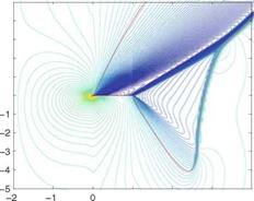
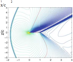
Results are shown in Fig. 4.14 of the flow past a 10% thick Quasi-Joukowski airfoil of unit chord with leading edge at the origin of the coordinate system, at incidence a = 10 °, near sonic conditions. The mesh system uses stretching and extends from x = —2 to x = 5 and from z = -10 to z = 50. Red lines represent
![]()
![]()
 Fig. 4.14 Iso-Mach lines of the near sonic flows: Top,
M0 = 0.9; Bottom,
 |
Mq = 1.1
x/c
sonic lines. The pressure distributions on the profile for the two cases are very similar, as can be seen from the Mach lines near the airfoil. This is associated with sonic freezing. Indeed, behind the bow shock in the M0 = 1.1 flow case, the Mach number will be close to M1 = 0.9, which explains why the flow features near the profile are very similar.
Commercial jet aircrafts cruise at Mach number in the vicinity of M = 0.85. In such condition, the profile will see a fairly large supersonic bubble on the upper surface terminated, in general, by a shock wave. In order to mitigate the wave drag, supercritical airfoil sections have been developed by Whitcomb and Clark [5]. Supercritical profiles, also called “peaky” profiles, tend to have a blunt nose followed by a rapid change of slope and a fairly flat upper surface to achieve a moderate shock strength by limiting the maximum value of the Mach number in the supersonic region. Shock-free airfoils have also been developed with inviscid codes for which the supersonic region is terminated by a smooth recompression. In practice, however, these shock-free airfoils may see a weak shock occur in place of the smooth transition from supersonic to subsonic, due to viscous/inviscid interaction as well as off-design flight conditions. For more details, see Boerstoel [6].


