Review of Rotor Reference Axes
There are several physical planes that can be used to describe the equations of motion of the rotor blades. These reference planes or axes systems have evolved as a matter of convenience, and each has advantages over others for certain types of analysis. However,
|
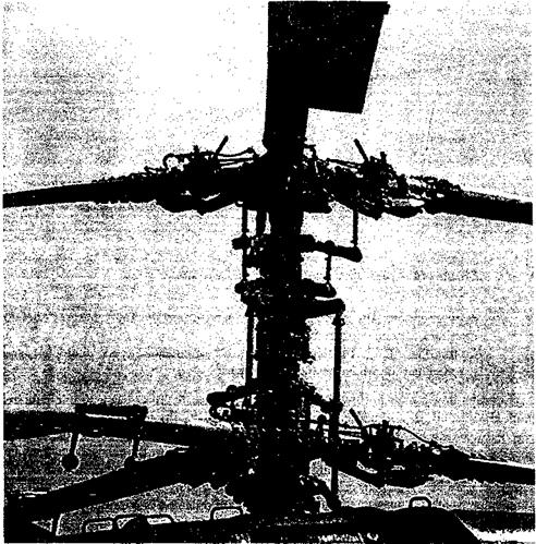
Figure 4.13 Hub of a coaxial rotor system showing the high level of mechanical complexity. |
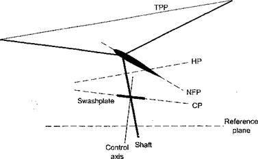
it is always possible to transform an analysis from one reference axis to another, as required. Figure 4.14 schematically shows the various reference planes and axes that are often used in helicopter analyses. These planes are:
1. Hub Plane (HP): The rotor hub plane is perpendicular to the rotor shaft. In the HP, an observer would see both blade flannina and feathering initr. h changes) during forward flight. While this plane is the most complicated for analysis of the rotor, it has the advantage of being linked to a physical part of the aircraft. The HP is often used for blade dynamic and flight dynamic analyses.
2. No Feathering Plane (NFP): This plane was first introduced by Gessow & Myers (1952). The NFP is a plane where an observer sees no variation in cyclic pitch, that is both вс and 6s are zero. However, the observer will still see a cyclic variation in blade flapping angle. Normally, this plane is used for performance analyses.
3. Tip Path Plane (TPP): This is the plane whose boundary is described by the blade tips. Therefore, an observer will see no variation in flapping, that is, both fc and
![]()
|
fiis will be zero. This plane is commonly used for aerodynamic analyses, such as rotor inflow or other wake models.
4. Control Plane (CP): This plane represents the commanded cyclic pitch plane and is sometimes known as the swashplate plane.
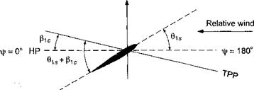
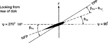
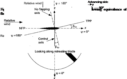
Consider now a rotor in forward flight and assume that the rotor has a simple flapping motion with only fic – that is, the rotor tilts forward by the amount fic as shown in Fig. 4.15. Notice that the relative amount of blade flapping versus feathering depends on the axis system to which the blade motion is being referenced. At fr = 0° we see that with respect to the NFP the blade flapping is full up, but the blade pitch is neutral (zero in this case). At ifr = 90°, with respect to the NFP the blade flapping is now zero, again with the pitch being neutral. However, at this azimuth the blade pitch is a maximum with respect to the TPP.
Now consider a more general case where the disk is tilted both forward and to the left. Again, as shown by Fig. 4.16, we see that the amount of blade feathering versus flapping depends on the axis system used to view the blade motion. Therefore, in light of this and the previous example, it is apparent that the amount of blade pitch (feathering) with respect to the TPP is equal to the amount of blade flapping with respect to the NFP. Fore and aft (longitudinal) flapping or fi[c with respect to the NFP is equivalent to lateral feathering (pitch) with respect to the TPP. Therefore, there is an equivalence of flapping and feathering motion. Strictly speaking, this equivalence is only true for a teetering type of rotor (where the flapping hinge is exactly at the rotational axis), but the equivalence is strong for all types of helicopter rotors. The results of this example are summarized in Table 4.1.
In the transformation from one plane to another, it will be apparent that
![]() file + — constant — (^ic)nfp — (^ь)трр •
file + — constant — (^ic)nfp — (^ь)трр •
Also, we have that
 |
Using the above relationships, it is possible to transfer any analysis from one reference system to another, that is, from the TPP to the NFP or vice versa. For example, the angles of attack in the TPP are related to those in the NFP by
(ог)трр = («)npp — (fiic + 0is). (4.76)
|
Table 4.1. Summary of Blade Motion with Respect to NFP and TPP
|
|
|
|
|
|
