Systems with One Degree of Freedom
The behavior of systems with one degree of freedom is of interest in its own right. Through the various forms of modal approximations, such as the Ritz and Galerkin methods (see Section 3.5), the behavior of complex systems frequently can be reduced to a set of equations each having the form of a single-degree-of-freedom system. Therefore, it is worthwhile to explore the various types of behavior we associate with such systems.
Consider a particle of mass m, restrained by a spring with elastic constant к and a damper with damping constant c, and forced with a function f (t) (Fig. 2.10). The governing equation can be written
mx + cx + kx = f (t) (2.66)
where x(t) is the single unknown, typically a displacement or rotation but not limited to such. Here, the mass m, the damping c, and the stiffness к are the system parameters and f (t) is a forcing function. Our interest in this system is limited for now in two special cases: (1) unforced motion, with f (t) as identically zero; and (2) harmonically forced motion.
1.4.3 Unforced Motion
Eq. (2.66) for unforced motion is given by
mx + cx + kx = 0 (2.67)
№
к
Az(t)

 |
Figure 2.10. Single-degree-of-freedom system
An exhaustive treatment of this equation is beyond the scope of this text. Suffice it to say that for our purposes, we are concerned with the qualitative aspects of the motion for various combinations of parameter values. We are interested in both positive and negative stiffness and damping. To facilitate exploration of the behavior, we define the natural frequency m such that к = mm2, divide the equation by m, and introduce the damping ratio Z so that c = 2mZm. Then, the equation of motion reduces to
x + 2Zmx + m2 x = 0 (2.68)
another advantageous step is to introduce dimensionless time f = mt, derivatives with respect to which are denoted by ()’. With this, Eq. (2.68) becomes
![]() x" + 2Z x’ + x = 0
x" + 2Z x’ + x = 0
We are mostly concerned about the response of systems with small damping ratios, in which Z < 1. For this case, the general solution is
![]() x(f) = e^Zf a cos ^/1 – Z2 f) + b sin ^/1 – Z2 f) x'(f) = e-Zf (by7 1 – Z2 – Za) cos ^/1 – Z2f)
x(f) = e^Zf a cos ^/1 – Z2 f) + b sin ^/1 – Z2 f) x'(f) = e-Zf (by7 1 – Z2 – Za) cos ^/1 – Z2f)
– (Z b + aj 1 – Z2) sin ^1 – Z2 f)
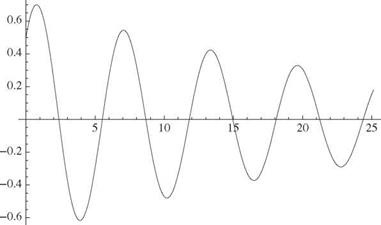
The responses caused by arbitrary initial displacement and velocity can be constructed by combining the responses to unit initial displacement and unit initial velocity. For the first, we let x(0) = 1 and x'(0) = 0, which together imply that a = 1 and b = Zll 1 – Z2. For the second, we let x(0) = 0 and x'(0) = 1, which together imply a = 0 and b = 1Д/1 – Z2. In all cases, the displacement and velocity both exhibit an oscillatory character with a decaying amplitude for Z > 0 and a growing amplitude for Z < 0. Positive damping leads to a decaying response signal (Fig. 2.11) and negative damping to a growing response signal (Fig. 2.12).
|
a cosh (ty/1 + Z 2) + b sinh (t^/1 + Z 2) |
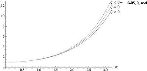
Actual mechanical systems always have positive stiffness. However, with the advent of active materials, it is possible to have a negative effective stiffness. Also, in the field of aeroelasticity, aerodynamics can contribute a negative stiffening effect that possibly overpowers the positive stiffness from the structure or the support. When a system has a negative effective stiffness, the response can be written as
This function is only slightly affected by the sign of Z and the initial conditions. Typical results are shown in Fig. 2.13. Response for negative stiffness is nonoscillatory divergent motion. Damping makes little difference when the stiffness is negative, although response is slightly larger for negative damping. In summary, when instabilities are encountered, the system response is divergent and may be either nonoscillatory or oscillatory.
|
Figure 2.11. Response for system with positive k and x(0) = x'(0) = 0.5, Z = 0.04 2.6.2 Harmonically Forced Motion |
We now consider the case of harmonically forced motion, where f (t) is a harmonic function of the form f (t) = kAcos(Qt). The response to harmonically excited motion is a subject worthy of study, but we hardly “scratch the surface” in this brief discussion. For the present purpose, we consider the equation of motion written as
mx + cx + kx = kAcos(Qt) (2.72)
Dividing through by m, we find
X + 2ZmX + a2 x = Am2 cos(Ut) = Aa? el at (2.73)
|
x(ф)
Figure 2.12. Response for system with positive k and x(0) = x'(0) = 0.5, Z = —0.04 |
with X as a complex variable and the actual displacement being found as the real part of x. Considering only the steady-state part of the response, we may assume
![]()
 |
x = Xe1 Ut
 |
||
Substitution of Eq. (2.74) into Eq. (2.73) yields
where G(i U) is the frequency response. This form allows us to write the solution as
![]() x = A| G(i U) | cos(Ut — ф)
x = A| G(i U) | cos(Ut — ф)
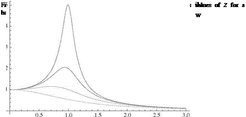
where | G(i U) | is known as the magnification factor, given by
and plotted in Fig. 2.14. The phase angle
shows the delay between the peaks in f (t) at t = 2nn/U, and the peaks in x(t) at t = ф/U + 2nn/U for n = 0,1,
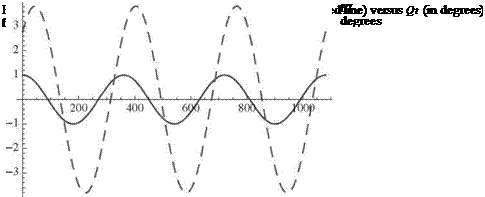
Now, as an example, we may consider a harmonic forcing function f (t) with A = 1 plotted along with x(t) for a particular choice Z and U/ш in Fig. 2.15. Here, the phase lag is noticeable as the response peaks are shifted approximately 43.45 degrees to the right.
 |
am
Harmonically forced systems also may exhibit a large and possibly dangerous response in the case of resonance, where the driving frequency Q is very near a. For undamped systems, the response grows as
A
2 [t sin(at) + cos(at)] (2.79)
whereas the response amplitude reaches 1/(2z ) for lightly damped systems.
1.5 Epilogue
 |
In this chapter, we laid out the foundational theories of mechanics that are needed for an introductory treatment of structural dynamics and aeroelasticity. It is hoped
that students find it helpful to be able to refer to these treatments as they are applied throughout the remainder of the text. Structural dynamics and aeroelasticity analyses of realistic aircraft structural elements may require more sophisticated theories, such as plate and shell theory and full three-dimensional finite-element analysis; however, such treatments are beyond the scope of this text.


