THE VELOCITY INDUCED BY A STRAIGHT VORTEX SEGMENT
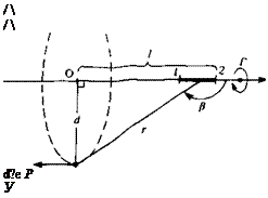
In this section, the velocity induced by a straight vortex line segment is derived, based on the Biot-Savart law. It is clear that a vortex line cannot start or end in a fluid, and the following discussion is aimed at developing the contribution of a segment that is a section of a continuous vortex line. The vortex segment is placed at an arbitrary orientation in the (x, y, z) frame with constant circulation Г, as shown in Fig. 2.14. The velocity induced by this
 |
FIGURE 2.14
Velocity induced by a straight vortex segment.
 |
From the figure it is clear that
d = r cos /3
d
l = d tan в and dl = —5— dp
cos p
Substituting these into Дqe
![]() —%To dP = T~Jsin P dP
—%To dP = T~Jsin P dP
cos P And
This equation can be integrated over a section (1—»2) of the straight vortex segment of Fig. 2.15
(<?e)1’2 = 4ndjp sin PdP = ^ (cos /^i – cos P2) (2.69)
The results of this equation are shown schematically in Fig. 2.15. Thus, the velocity induced by a straight vortex segment is a function of its strength Г, the distance d, and the two view angles /3,, p2.
For the two-dimensional case (infinite vortex length) рг=0, p2~ л and
 (2.70)
For the semi-infinite vortex line that starts at point О in Fig. 2.14, /31 = л/2 and p2 = л and the induced velocity is
 (2.71)
which is exactly half of the previous value.
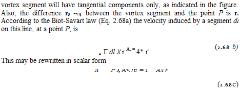
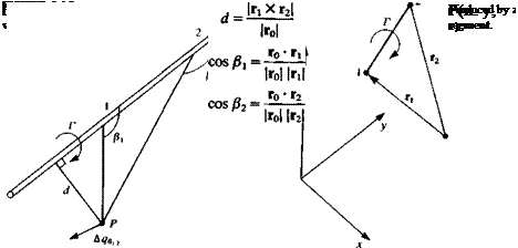
Equation (2.68b) can be modified to a form that is more convenient for numerical computations by using the definitions of Fig. 2.16. For the general three-dimensional case the two edges of the vortex segment will be located by Г! and r2 and the vector connecting the edges is
ro = r2 – rl
FIGURE 2.16
 |
as shown in Fig. 2.16. The distance d, and the cosines of the angles /3 are then
The direction of the velocity qt 2 is normal to the plane created by the point P and the vortex edges 1, 2 and is given by
fi Xr2
ІГі X r2|
and by substituting these quantities, and by multiplying with this directional vector the induced velocity is
 (2.72)
A more detailed procedure for using this formula when the (x, y, z) values of the points 1, 2, and P are known is provided in Section 10.4.5.


