Wind-tunnel balances
 |
To measure the forces exerted by the airflow, the model is normally mounted on to a balance which may be a mechanical or an electrical type. The older mechanical force balance is rather like a simple weighing machine of the type used to weigh babies or patients in a hospital. As illustrated in Fig. 2.16, the force to be measured (such as the lift on the model) is applied via a series of levers and
![]() A simple balance
A simple balance
![]()
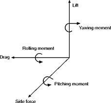
pivots or flexures to an arm upon which is placed a jockey weight. The moment of the applied force is balanced by moving the jockey weight along the arm. The position of the jockey weight therefore indicates the magnitude of the force. The further along the arm the jockey weight has to be moved, the greater is the force being balanced. The same principle is used to measure horizontal drag or thrust forces, as shown in Fig. 2.16. One arm has to be used for each of the three forces and three moments that make up the six ‘components’ illustrated in Fig. 2.17. In small college tunnels it is normal to have only three arms which measure the three most important components, lift, drag and pitching moment. The design of the levers and pivots is very complicated because it is important that a change in the vertical lift force does not affect the arm that is supposed to measure only the horizontal drag force. The balance unit which is large is situated outside the tunnel, and the model is attached to it by means of a number of rods or wires (see Fig. 2D, earlier). Originally the jockey weights were moved by hand, but nowadays they can either be moved automatically by a servo electric motor, or are left fixed, with the force of the arm being measured by an electrical force transducer. A force transducer is an instrument that produces an electrical output that is proportional to the applied force. This brings us to the second form of balance, the electronic type.
The electronic force balance consists of a carefully machined block of metal that is attached to the model at one end and to a supporting structure at the other; this often takes the form of a single rod or ‘sting’ protruding from the rear of the model. Electrical resistance strain gauges attached to the block produce output voltages proportional to the applied forces. Up to six components can be measured. This type of balance is very small and compact and is normally contained within the model. One potential disadvantage is that there is usually a certain amount of unwanted interference between the different components; changes in lift affect the drag reading, etc. However, the computer-based data acquisition systems to which such balances are invariably attached are able to make corrections and allowances automatically.
|
|


