Compressibility Losses and Tip Relief
 |
|||
Gessow & Crim (1956) have estimated the additional effects of compressibility on the overall rotor profile power requirements when the tip of the advancing blade approaches and exceeds the drag divergence Mach number Mdd of the airfoil sections. Their results were obtained using blade element theory combined with 2-D airfoil section characteristics. By fitting a curve to their results, Johnson (1980) suggests that the extra rotor profile power with compressibility effects can be approximated by
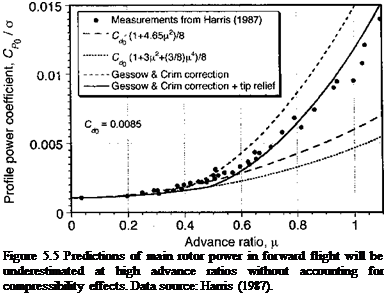
where A Mdd is the amount the advancing blade tip Mach number exceeds the drag divergence Mach number of the airfoil section, that is, A Mdd — Mi,90 — Mdd, where Mi,90 is the tip value at r = 1 and 1jr = 90°. Values for Mdd must be obtained from tests on 2-D airfoils (see Chapter 7). Generally, it is found that the drag on an airfoil remains nominally constant and independent of Mach number until Mdd is reached. The result of the Gessow & Crim correction to the profile power is shown in Fig. 5.5 when added to Eq. 5.29, where it is apparent that this model overpredicts the profile power. However, by making allowance for so-called tip relief effects (see next) by increasing the effective drag divergence Mach number of sections near the tip, the agreement with the measured results is better. See also Norman & Sultany (1965).
Similar techniques can be developed to account separately for the effects of stall on rotor
nmx/pr — fTiictafcnn Яг ЛЛЧ/^rc ГОД£Л friictafcnn Яг Гтрсспш япН Amp. r flQSS’l
fSXSTTWA UVV ^ A TAJ WA ^ уЛ/ 1 ^/5 WW WWUWWTT • ‘ /9 XAAAAWA
While these techniques are by no means exact, they allow a relatively simple estimate of compressibility and blade stall effects on rotor performance predictions and so are suitable for preliminary design purposes.
 |
Harris (1987) suggests another approximation for the profile power increase from compressibility effects with blades of different thickness-to-chord ratios (t/с). The result is
based on transonic similarity rules by using
![]()
![]() ACPo _ 0.3 (1 + fi)5/2 0t/cf /2 (M + l)2 for Mli90 > Мм
ACPo _ 0.3 (1 + fi)5/2 0t/cf /2 (M + l)2 for Mli90 > Мм
|
|
|
for Mі 90 < Mdd, |
where
(Mli90)2 – 1
1.79(Mij90)4/3(r/c)2/3
A more detailed analysis of compressibility effects on the rotor must represent the actual nonlinear airfoil characteristics as functions of Mach number through stall at each blade element, including 3-D effects, followed by integrating numerically to find the effects on rotor thrust and power. Some allowance for an effect known as tip-relief should normally be included in any such power calculation. Tip relief accounts for the relaxation of compressibility effects at the edge of a lifting surface of finite span, and approximations for the effect can also be developed based on transonic similarity rules. The effect was first noted in experiments on propellers, which showed that losses in propulsion efficiency did not occur until the tip Mach numbers well exceeded the drag divergence Mach number of the blade tip sections estimated from 2-D considerations. One practical analysis of tip-relief effects is given by Prouty (1971, 1986), although several approximations are involved. See also LeNard (1972) and LeNard & Boehler (1973).
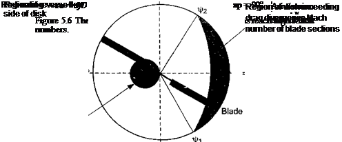
The region of the rotor disk affected by compressibility effects is shown in Fig. 5.6 and can be defined by finding where the incident Mach number of the flow that is normal to the leading of the blade exceeds the drag divergence Mach number Mdd• For an unswept blade the incident Mach number is
![]() Mr^ = MsiR (r + li sin }r),
Mr^ = MsiR (r + li sin }r),
where MqR is the hover tip Mach number. This means that the region of the disk affected by compressibility effects is defined by
![]() M^R (r – f д sin fr) > Mdd or that r + д sin xfr > —————
M^R (r – f д sin fr) > Mdd or that r + д sin xfr > —————
 |
Mqr
The azimuth angle for the onset of drag divergence (fi) can be obtained by setting r = 1 so that
The symmetry of the problem suggests that the tip section leaves the drag divergence zone at xj/2 — 180° — f і. The parts of the blade in the drag divergence region can be found using
![]()
![]() гм = ~ MsiniAj
гм = ~ MsiniAj
![]()
![]() The increment in profile power associated with this region on the disk will be АС г 1 г*2 rl
The increment in profile power associated with this region on the disk will be АС г 1 г*2 rl
Jrdd
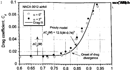
where ACd is the extra drag on the blade section when it exceeds the drag divergence Mach number Mdd• For the NACA 0012 airfoil, Prouty (1986) suggests that this be approximated by
[ 12.5(M — 0.74)3 for M > 0.74
ACd(M) = (5.38)
10 otherwise.
For lower Mach numbers the drag stays fairly constant (see also Fig. 7.43). As shown in Fig. 5.7, this model gives good agreement with 2-D drag measurements.
 |
Tip relief effects can be accounted for in the blade element theory (BET) using an effective local Mach number Meff at each blade element in the tip region that exceeds the drag divergence Mach number, that is, Mr ^ > Mdd. One method suggested by Prouty (1986) is to define the effective Mach number as
Section Mach number, M
0. 005
 СЛ
СЛ
0 0>
^ 0.004
5
0. 003
(D
1
CL
E
8 0.002
E 0
0. 001
о
<
0
0. 8 0.85 0.9 0.95 1
Advancing blade tip Mach number, M gg
where Mddi is the 2-D value of the drag divergence Mach number (i. e., from the data in Fig. 5.7) and Mdd3 is the 3-D value with tip relief. In most cases it is found from finite wing measurements that Mddb exceeds Mddi by 10-15%. The parameter ARbiade is the aspect ratio of the blade (i. e., R/c). Equation 5.39 is used in Eq. 5.37 to compute the relieving effects of the 3-D flow about the extreme tip of the blade.
~ ____ тт: „ с о u: л_____ ^ л _________________ ~ _
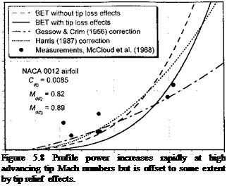
1 lie lCSUllS 111 rig. J. O S11UW 11ШІ ill lllgn ilUViUlWlllg up IVlilWll UUUIUCIS uic piunic puwci
increases rapidly, although it is offset to some extent by tip relief effects. It would appear that the corrections suggested by Gessow & Crim (Eq. 5.30) and Harris (Eq. 5.31) give reasonable results bearing in mind the relative simplicity of these equations. Notice that Mdd is also a function of AoA of the airfoil section (see Chapter 7) and the thrust on the rotor. The relationship between Mdd and the rotor mean lift coefficient can be approximated empirically – see Stepniewski & Keys (1984) and Prouty (1986). The effects of a swept tip serve to further modify these results, but can be accounted for approximately by using an incident Mach number that is normal to the leading edge of the blade. In such a case the incident Mach number is
Mr<f — Mqr (г + д sin V0 cos A, (5.40)
where A is the local sweep angle. See also Section 6.4.6 on swept tips.


