Configuration
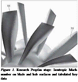
A research propfan stage is used for the investigation (Wallscheid et al, 1998). The configuration is presented in Fig. 1 together with some tabulated key data. The propfan stage is a scaled rig stage. It consists of two counterrotating rotors and no vanes. The design operating point is investigated where the fow is transonic for both rotors (see Fig. 1). The simulation is threedimensional and viscous, and also considers the tip gap between the rotors and the casing. For the simulation, the original blade count of 10:12 is reduced
to 5:6. This leaves the blade count ratio, the operating point, and the interblade phase angle unchanged.
|
no. blades Rotor-1 |
10 |
|
no. blades Rotor-II |
12 |
|
RPM Rotor-I |
-4980 |
|
RPM Rotor-II |
4316 |
|
Total Pressure Ratio |
1.24 |
|
Entry Mach number |
0.7-0.75 |
|
Exit Mach number |
0.65-0.68 |
|
Outer Diameter |
1m |
|
Reynolds-Number |
2.3 mill. |
 |
The aerodynamic interactions between the blades – mainly the upstream running shock and the downstream convected wake – excite the rotor blades to vibration. This forced-response-excitation that appears at the blade passing frequency is investigated in the current aeroelastic study. For each rotor blade, the eigenmodes of vibration with an eigenfrequency close to the excitation frequency are sensitive to this excitation. Here, the excitations of the first and second rotor are investigated at the same time in one common simulation. For each rotor, one eigenmode of blade vibration is considered, the eigenmode with its eigenfrequency closest to the exciting blade passing frequency (remember the Campbell diagram). The original three-dimensional blade vibration mode shapes are used (Fig. 2). The mode shapes of interest feature a highly threedimensional pattern due to the high excitation frequency of the blade row interaction. This is fully taken into consideration in the current three-dimensional simulation. In order to have a high level of excitation in the numerical study, the blade eigenfrequencies are adapted to the excitation frequency. The study neglects structural damping, i. e. only the aerodynamic damping of the blades balances the excitation of the blade passing.
With the fliid-structure coupled method, the full aeroelastic propfan configuration is simulated. The simulation includes at the same time the blade passing and the induced blade vibrations.
The results from the fluid-structure coupled aeroelastic computation are compared with results obtained from a linear forced response analysis. The lat-
|
Figure 2. Eigenmodes (No. 12 for Rotor-I, No. 10 for Rotor-II) |
ter uses aerodynamic solutions that are computed on the same meshes and by the same non-linear aerodynamic method as before. A simulation of the blade- row-interaction of the stage with stiff blades yields the aerodynamic forcing. The aerodynamic damping is computed from further non-linear aerodynamic simulations of each rotor alone where the blade vibration is prescribed as harmonic motion in the eigenmode under investigation. The solution of the forced response problem is then obtained by the combination of both results. This procedure makes use of the aerodynamic superposition principle and is typical of the analysis procedure currently applied within industry. This decoupled approach will be referred to as the linear solution to the forced-response-problem. It uses the aerodynamic solutions of a non-linear aerodynamic method. A linearized aerodynamic method (a frequency domain solver) was not used in the current study.


