DYNAMIC EFFECTS
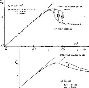
Fluctuations of Lift. Lifting characteristics as obtained from wind-tunnel tests, and in the form as presented in tunnel reports, are misleading insofar as the lift at and around CLX is sometimes not as steady as it appears. Speeds in air are so high, and the inertia and the damping of the wind-tunnel balances are large enough, so that a time-averaged values of lift and other forces and moments are recorded. A particular characteristic of fluid-dynamic testing in water (in a water tunnel or towing tank) is, on the other hand, the fact that the speeds required to obtain a certain Reynolds number are but a fraction (possibly a few percent) of those in wind tunnels. As a consequence, fluctuations of lift can “easily” be read from the balance. Lift as a function of the angle of attack from a water tunnel test at 2.4 m/sec = 6 ft/sec is plotted in figure 35 for two foil sections. Quoting from (31), the lift of the NACA 0012 section fluctuates “at” C^ , irregularly up and down as indicated in the illustration. The cambered and round-nosed section Go-387, displays similar (if lesser) fluctuations at angles of attack beyond CLX, over an extended range of that angle. The frequency “f” of these fluctuations as tested, is between 0.2 and 1.0 per second which, at a speed of 2.4 m/sec, leads to the non- dimensional value of
f c/V = between 0.03 and 0.16 (19)
|
|
_______ u_L___________ і_____________ і____
/ О 10 20
Figure 35. Lift as tested in a water tunnel (31) showing fluctuations in the vicinity of the maximum coefficient.
Dynamic Lift Stall. When a wing or a two-dimensional airfoil approaches the stall angle at a significant rate, such as might be encountered with a sudden pull-up of the airplane, the angle of attack for stall and the maximum lift coefficient are increased (32,a) as compared to the steady state flow case. When the dynamic change of angle of attack reverses the flow on the airfoil the lift does not revert to the value encountered at the lower angles, but will fall below these values. This results in lift coefficients below the values for the steady state case and causes a hysteresis loop as illustrated in figure 36. This tendency for a lift overshoot and a hysteresis loop is encountered in almost any dynamic situation of airfoils, and is especially important in the designs of helicopter, propeller and compressor blades as it may lead to stall flutter. Stall flutter of a blade can result in very high values of torsional stress as well as undesirable vibrations.
The dynamic lift overshoot is also important in the operation of an aircraft, since a sudden pull-up can produce an effective sudden stall even if the wing is one which displays a gentle type stall under steady state conditions. This may cause difficulties, especially under emergency conditions.
|
Figure 36. Frequency effect on hysteresis loop for oscillation airfoil (32,i). |
(31) Investigation of foil sections in a water tunnel.
a) Hoerner, 0012 and Go-387, Fieseler W’Tunnel Rpt 3 (1939).
The dynamic lift overshoot is caused by a delay of the adverse pressure gradient, allowing the airfoil to support greater lift than during the steady state case. The oscillating airfoil derives lift from the frequency induced normal velocity and the effects of the change in the rate of angle of attack (32,b). The frequency induced velocity normal to the airfoil effectively results in an increase in the section camber as ot increases and a corresponding decrease as or is reduced. Thus, the rate of change of angle of attack, o’ , effectively increases and decreases the angle of attack compared to the static case. Since a certain amount of time is required for the boundary layer to build up, separation is delayed and the airfoil responds to the dynamic angle of attack change without stall, also contributing to the lift overshoot (32,c).
The combination of the q and the o’ effects influences the shape of the hysteresis loop which is a function of the reduced frequency defined by (32,d)
к = сш/V or = c lu/V0 (20)
where ш is the oscillation frequency, c is the mean aerodynamic chord and c is the 2-dimensional chord length. The reduced frequency is thus a measure of the rate of change of oscillation with respect to the free stream velocity. The reduced frequency given in equation (20) is normally considered applicable only for incompressible flow cases. For the compressible flow case at Mach numbers below the critical the reduced frequency will be
к = с ш/V0 >|T”— M (21)
where M is the free stream Mach number.
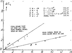
The maximum lift coefficient overshoot, ACLxd, due to the dynamic condition at which it occurs, iWxd, is a function of the section shape, Reynolds number, type of stall and the reduced frequency. Test data (32,f) indicates that for a given level of reduced frequency AC|_xd reduces with increasing camber and, although CLX under static conditions changes with Reynolds and Mach numbers, the lift overshoot is not effected. Under dynamic conditions, however, the level of turbulence increases with the reduced frequency which could give higher values of LCLx6 than would beq>redicted by dynamic effects alone. This, along with the turbulence in the propeller slipstream may explain the large difference between the test data of (32,a) and (32,g), figure 37.
The basic shape of the dynamic lift curve through stall is dependent on the type of stall in the same way as airfoils operating at steady state conditions, figure (38). Thus, trailing edge stall will tend to yield a more rounded stall shape than leading edge stall. The reduced frequency and the type of motion effect the stalling, and it appears the stall becomes sharper as the frequency increases figure 38.
|
C/VQ — ^ DEGREES dt Figure 37. Lift increase due to dynamic change of angle of attack. |
The shape of the lift hysteresis curve, figure 36, depends on the airfoil shape, reduced frequency, the initial angle and angle of attack range of the test. If the initial angle of attack and change is below the static stall angle the hysteresis loop will be very small and on the static lift curve slope. However, if the initial angle and increment allow the static stall angle to be exceeded the loop can be large as shown on figure 36.
From figure 37 the lift overshoot can be estimated as a function of the pitch rate velocity and mean aerodynamic chord. The considerable scatter in the test data is caused by changes in section, turbulence and Reynolds number which influence the basic maximum lift of the section.
Although many experimental investigations of dynamic lift stall have been undertaken (32), it is desirable to have a means for predicting the angle overshoot and the shape of the hysteresis loop as a function of the instantaneous angle of attack from the available static airfoil data. An approximate method based on the concept of induced camber, attached flow phase lag and reduced frequency (32,d) appears to give a good first approximation.
(32) Dynamic Lift Stall:
a) Gadeberg, JB. L., Dynamic Aircraft Stall, NACA TN 2525.
b) Ericsson, L. E., J of Aircraft, Vol 4 No. 5, 1967.
c) Moore, F. K., Lift Hysteresis – Boundary Layer, NACA TN 1291.
d) Ericsson, L. E. & Reding, J. P., J. A/C, Vol 8 No. 8 & Vol 8 No. 7.
e) Halfman, R. L., Johnson, H. C. & Haley, S. M., NACA TN 2533.
f) Conner, F., Willey, C. and Twomey, W., NASA CR 321.
g) Davis and Sweberg, NACA TN 1639.
h) Harper, P., Rate Change on CLX, NACA TN 2061.
i) Liiva, Jaan, Unsteady Lift, J. Aircraft, Vol. 6, No. 1.


