Forward Flight Performance
For a helicopter in forward flight, the total power required at the rotor, P, can be expressed by the equation
P = Pi + P0 + Pp + Pc, (5.17)
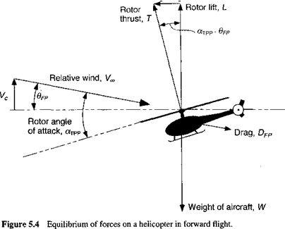
where P, is the induced power, Po is the profile power required to overcome viscous losses at the rotor, Pp is the parasitic power required to overcome the drag of the helicopter, and Pc is the climb power required to increase the gravitational potential of the helicopter. Consider the equilibrium of forces on a single rotor helicopter in a climbing forward flight situation, as shown in Fig. 5.4. In the figure 6pp is the flight path angle, so that for small angles the climb velocity, Vc = Vqqврр. For small angles, satisfying vertical equilibrium gives the equation
![]()
![]()
 |
T cos(ofxpp — ®fp) — W ^ T.
Satisfying horizontal equilibrium leads to T sin(ofxpp — Opp) = Dpp cos 6pp.
Assuming Dfp is independent of the angle of climb, then this latter equation simplifies to
![]()
 |
T (атрр — @fp) = D.
Rearranging and solving for the disk AoA, orTPP, gives
огтрр = Opp + —. (5.21)
Vv
Now, consider the power to undertake a climb (and also to propel the helicopter forward). This part of the power is
The term WVC is known as the climb power, Pc. The term DVqq is known as the parasitic power, Pp, because this is energy lost to viscous effects.
5.4.1 Induced Power
It is already known from the simple 1-D momentum theory described in Chapter 2 that the induced power of the rotor, P,, can be approximated as
Pi — kT Vi. (5.23)
If the forward velocity is sufficiently high, say pc > 0.1, then the induced velocity can be approximated by the asymptotic result predicted by Glauert’s “high-speed” flight formula
given by Eq. 2.114. Therefore, the power equation can be written more simply as
![]()
![]() (5.24)
(5.24)
where к is the now familiar empirical correction to account for a multitude of aerodynamic phenomena, mainly those resulting from tip losses and nonuniform inflow. The value of к cannot necessarily be assumed independent of advance ratio, but the use of a mean value between 1.15 and 1.25 is usually sufficiently accurate for preliminary predictions of rotor power requirements. The previous equation shows the origin of the constituent terms that comprise the basic power requirements of the helicopter in forward flight. Note that in coefficient form the induced power can be written as
![]() (5.25)
(5.25)
5.4.2 Blade Profile Power
Glauert (1926) and Bennett (1940) were among the first to formally establish estimates of profile power using the blade element theory. The profile power coefficient with a uniform blade chord is
![]() (5.26)
(5.26)
where U is the resultant velocity at the element and Cj0 is the profile drag coefficient of the airfoils that make up the rotor blades. The inclusion of the radial component of the velocity at the blade element means U2 = Uj + U, where Ur — QR/л cos fi. Neglecting the radial flow component Ur such that U — Ur = QR(r + /x sin if) gives
![]() (5.27)
(5.27)
 |
Expanding and integrating gives
(5.28)
The results from the analysis of Glauert (1926) and Bennett (1940) show that the profile drag can be approximated as
where the numerical value of К varies from 4.5 in hover to 5 at /x = 0.5, depending on the various assumptions and/or approximations that are made. In practice, usually average values of К are used that are independent of advance ratio. Bennett (1940) used an average value of К = 4.65, while Stepniewski (1973) suggests К — 4.7. Either value will be acceptable for basic performance studies at the advance ratios typical of conventional helicopters, that is, for /x < 0.5. At higher advance ratios, experimental evidence suggests that profile power grows more quickly than given by Eq. 5.29, as shown in Fig. 5.5. This is a result of radial and reverse flow, as well as compressibility effects on the rotor.


