Semi-Rigid or Hingeless Rotors
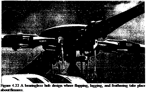
In the semi-rigid type of hub design, the flap and lag hinges are replaced by flexures (Fig. 4.22), which are normally built out of advanced composite materials. This eliminates the complexity, weight, and maintenance that is associated with the use of mechanical hinges and bearings. There are many different types of semi-rigid or hingeless hub designs. If the feathering bearing is also replaced by a flexible element, it is called a bearingless hub design.
 |
The analysis of the semi-rigid blade proceeds by assuming that the flexure provides an equivalent spring stiffness kp at an equivalent hinge offset e. In this case, the equation of motion becomes
I m(y – eRffidy +’ / m(y – eR)p£l2ydy + kp(fi – fp) — / Fz(y – eR)dy, JeR JeR JeR
(4.97)
where all the symbols have their usual meaning and ftp is the pre-cone angle. This precone angle is designed into the hub and blade to reduce the steady flapping moments about the hinge (like the underslung teetering design) and typically would be about 2-3°. The foregoing equation can be written in conventional form as
2
$ + Vpf = у Mp + (4.98)
where coq is the nonrotating flapping frequency as given by coq = у/kp/Ip. The natural frequency of flapping is
where it has been assumed that Ip « lb. Notice that the flapping frequency is now affected by both the CF forces and the elastic bending stiffness of the hub. If coq = 0, then the result reduces to that for an articulated rotor.
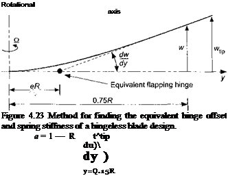
The equivalent hinge offset and flap stiffness can be determined approximately by comparing the deflected slope of the blade at the root to a point further out on the blade (normally 75% radius), as shown in Fig. 4,23. The majority of the curvature is in the hub region at
 |
|
the flexure and the remainder of the blade is essentially straight. The equivalent offset e is given by
|
кв = iBn[18] [19] ( |
and the effective spring stiffness is
A similar approach can be used for the lagging direction. This means that the analysis of the hingeless rotor design can proceed using all the same methods of analysis used for the articulated rotor, but with a corrected effective hinge offset and flapping frequency.


