Vortex Filaments and the Biot-Savart Law
In the preceding section on vortices the velocity distribution was obtained in two-dimensions by imposing the condition of irrotationality on purely tangential flow. This led to the concept of the point vortex in which the flow is irrotational everywhere except at a singular point that defines the center of the vortex. The closed line integral (f> V-гЖ is zero for any contour not enclosing the singularity. If the singularity is enclosed by the contour, the integral has a value Г different from zero defined as the strength of the vortex.
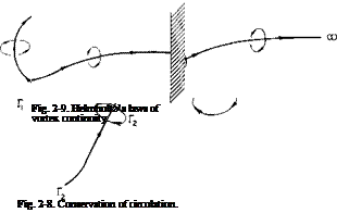
This concept can be extended to three-dimensions by imagining a line that is the locus of singular points of constant strength such that the closed line integral cfV’t/R evaluated around any contour enclosing the line is equal to the strength Г and vanishes for any closed contour not enclosing the line. Such a line, referred to as a vortex filament, is illustrated in Fig. 2-8, in which two vortex filaments of strengths Г, and Г2 are shown. This figure also illustrates the fact that if the contour encloses two or more vortex filaments the value of the closed-line integral of the velocity will equal the sum of the strengths of the vortex filaments interior to the contour.
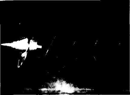
An important theorem of vortex behavior, attributed to Helmholtz and illustrated in Fig. 2-9, states that a vortex cannot terminate in a fluid but must either close on itself, extend to infinity, or terminate at a solid boundary. The first possibility is aptly illustrated by the familiar smoke ring. Figure 2-10 illustrates vortex filaments trailing from the blade tips of a marine propeller and extending for a considerable distance downstream. In this example the center of the vortex filaments is made visible by the occurrence of cavitation in the region of reduced static pressure.
Another important behavior to keep in mind with regard to vortex filaments is the fact that they must lie along streamlines. This follows from Eq. (2-13) which shows that in the absence of nonconservative forces the rotation of fluid particles (which travel along streamlines) remains constant. Hence fluid particles that compose the rotational motion at the singular
points along the vortex filament remain in rotation as they travel through the flow field.
 |
Associated with a vortex filament is a velocity field, commonly referred
to as the induced velocity, which can be calculated by means of the Biot – Savart law. The derivation of this law [1] is beyond the scope of this book but is stated in vector differential form as
![]() ^ _ У r X
^ _ У r X
|
Fig. 2-10. Tip-vortex cavitation produced by a marine propeller. (Garfield Thomas Water Tunnel, The Pennsylvania State University) |
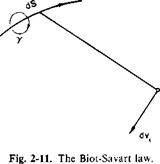
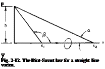
Refer now to Fig. 2-11: <7v, is the differential velocity induced at point P by the directed differential length of vortex dS, у is the circulation around the element dS and is directed in accordance with the right-hand rule of rotation; r is the vector from P to the elemental length dS. This is felt to be the most useful form of the Biot-Savart law, special cases of which can be found in the literature. Consider, for example, Fig. 2-12. Here a straight-line vortex filament lies along the x-axis and extends from x1 to x2. (At these points the vortex may take a 90° turn or it may be that we are interested only in the contribution made by the part lying between xt and x2 of an infinitely long vortex. At any rate the vortex cannot terminate at xi or x2.) Consider the velocity induced by this vortex line at the point 0, y. For this situation the equation of the vortex line is R = ix, so that
dS = c/R = і dx
and
ІУ + r = R
a, /і, and h are shown in Fig. 2-12.
Observe that if a and /? = 0, as they do when the line extends from — go to + oo, Eq. (2-39) reduces to (2-30), the velocity induced by a point vortex in two-dimensional flow.
 |
Sometimes it is extremely difficult to evaluate Eq. (2-39) for a given vortex system. In this case we can resort to numerical integration on a digital
computer or to the use of a direct analog computer described in Ref. 2. Here use is made of the fact that the magnetic field around a current – carrying wire is determined by an equation of exactly the same form as (2-39).
Although the methods of potential flow are very useful and powerful, often we cannot apply them because of what is termed “real fluid effects.” On some of these occasions compressibility or viscous effects can be accounted for by properly modifying Euler’s equation to include viscous shearing forces and the variation of the density with pressure. However, to
 |
solve the more exact nonlinear differential equations for all but the simplest of boundary conditions is extremely difficult. Hence much of aerodynamics is, of necessity, based on experimental data.


