Drag Estimation
It has been said that the most valuable wind-tunnel test engineer is one who can predict the results before the tests are performed. This is sometimes true, because the configurations under test have already been designed and half completed. Irrespective of this point, it is important that the V/STOL aerodynamicist or the designer have an appreciation of the factors that influence the parasite drag and be capable of making reliable drag estimates.
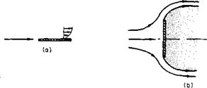
In order to estimate the drag of a body or to design a body for minimum drag, it is necessary to understand the origin and mechanism of the aerodynamic drag produced by a body. D’Alembert’s paradox states that in an inviscid fluid a body can experience no drag. This can be proved relatively easily by use of the momentum theorem. Why then does a body experience drag in a real fluid? If we exclude the induced drag associated with the lift produced by a body, the parasite drag is composed of two parts, the skin friction drag and the form drag. These parts may be of equal magnitude or the one may completely overshadow the other, depending on the shape of the body. The skin friction drag is the result of the shearing stresses in the fluid as it passes over the surface of the body. The form drag results from the unbalance in normal pressure forces around the body due to the separation of the flow. Perhaps, these statements can be clarified by referring to the drag of a flat plate at first aligned with the flow and then positioned normal to the flow, as in Fig. 2-13.
In Fig. 2-13a the drag is entirely the result of skin friction, whereas in Fig. 2-136 it is entirely form drag. If some means could be used to prevent
separation of the flow at the edges of the plate in Fig. 2-136, the drag could be reduced to zero.
The flat plate is rather an extreme with regard to both types of drag. To reflect further on the drag make-up, consider the typical body in Fig. 2-14.
Consider the fluid adjacent to the body as it flows aft from the nose. At the nose a laminar boundary layer starts to grow. The pressure is lower at
|
Fig. 2-13. Types of drag: (a) friction drag; (b) form drag. |
2 than at 1, which is favorable to the flow, and the laminar boundary layer is maintained. Somewhere around 2 the flow passes through a minimum pressure peak. Thereafter the pressure gradient is an adverse one and the boundary layer thickens rapidly. At some point near 2, depending on the pressure distribution, body roughness, and Reynolds number, the boundary layer transists from a laminar to a turbulent boundary layer, called the transition point. The turbulent boundary layer continues to thicken until the flow is no longer able to remain attached to the body and separates.
|
Fig. 2-14. Boundary layer growth and separation on a body shape. |
This is called the separation point. From there on, around the rear of the body, a turbulent wake exists in which the pressure acting on the surface is nearly constant and of a lower value than would have existed had the flow remained unseparated. This low pressure acting over the after portion of the body results in the form drag.
If the Reynolds number of the flow is sufficiently low, a laminar boundary layer will be maintained over a greater portion of the body and, in fact, can separate from the body before ever transisting to a turbulent layer. If this
 |
 |
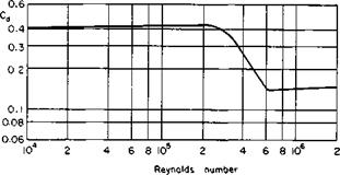
separation occurs, the separation point will be farther forward on the body, and the form drag will be correspondingly higher. The ability of the turbulent boundary layer to remain attached longer than a laminar layer is attributed to the turbulent eddies that bring into the boundary layer the higher-energy flow of the outer stream. There is a particular Reynolds number, referred to as the critical Reynolds number, for which the point of transition and point of laminar separation are coincident. Any increase in Reynolds number beyond this value will result in the transition of the laminar layer to a turbulent one before separating. The separation point will then shift farther back on the body and there will be an attendant decrease in the drag. For a rather blunt body, but with a definite degree of roundness, this effect is pronounced. The drag coefficient for this type of body as a
Fig. 2-15. Comparison between variation of drag coefficient with Reynolds number for rounded
and blunt bodies.
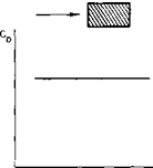
function of Reynolds number is given qualitatively in Fig. 2-15a. For a body with very sharp edges, which fix the point of separation regardless of the Reynolds number, the drag coefficient is nearly constant and independent of Reynolds number, as shown in Fig. 2-5b. A streamlined shape exhibits only a slight critical Reynolds effect or none at all if suitably streamlined. Since most of its drag will be caused by skin friction, the CD of a streamlined body will show a gradual decrease with increasing Reynolds number.
Attempts to predict quantitatively the drag of a given shape are, in general, not too successful. However, a qualitative understanding of the origin and nature of the drag is helpful to the aerodynamicist and designer.
Most airplane manufacturers, both helicopter and fixed-wing, have their own tests from which drag estimates for future designs can be made. In addition, considerable data have been compiled and published about the drag of aerodynamic shapes, including complete airplanes and the drag components. Reference 3 is an excellent source of information on drag and
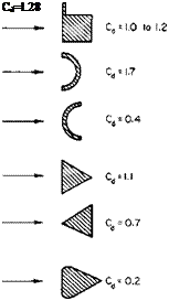
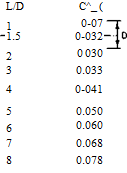
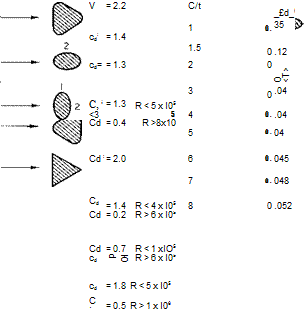
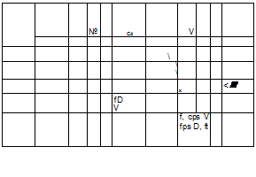
its estimation. In addition, Refs. 4 through 7 are recommended as sources of drag data for various shapes. No extensive presentation of drag data is given here. However, Figs. 2-16 through 2-20 present a limited amount of data taken from various sources with which preliminary drag estimates can be made.
 |
 |
For making preliminary estimates of the drag of an aircraft it is sometimes convenient to base the drag on that of another aircraft with about the same degree of streamlining. The drag of the reference aircraft is then scaled
Fig. 2-16. Drag of various three-dimensional shapes (Cd based on projected frontal area).
according to its wetted area, in terms of which drag can be expressed as an average skin friction drag coefficient Cf :
D = jpV2SwCf.
Often the drag of an aircraft is also expressed in terms of so many square feet of equivalent flat plate area/ with a CD of 1.0:
D = pV2f
Hence
 |
|
Cd= 1.98
Fig. 2-17. Drag of various two-dimensional shapes (Cd based on projected frontal area).
![]()
![]()
![]() 2.0
2.0
1.0
0.8
0.6
0.4
0.3
0.2
0.1
Reynolds number
Fig. 2-18. Drag of circular cylinders and Strouhal number.
For a typical light aircraft with fixed gear Cf is approximately 0.013. A well-streamlined World War II propeller-driven fighter had a Cf of about 0.004, whereas current turbojet aircraft have Cf values of approximately 0.003.
|
Fig. 2-19. Drag of sphere. |
|
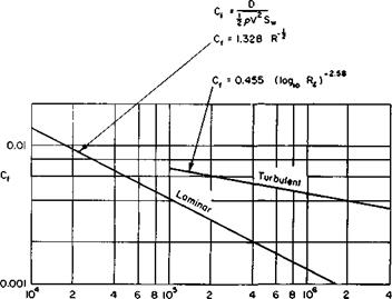
Fig. 2-20. Laminar and turbulent skin-friction drag of flat plates (based on wetted area). |
|
|
Airfoil Families and Characteristics
The predecessor of the National Aeronautics and Space Administration (NASA) was the National Advisory Committee for Aeronautics. NACA, over a period of about 15 years in the 1930’s and 1940’s, developed and
tested families of airfoils beginning with the four – and five-digit series on through laminar flow and high-speed sections. To discuss completely all of these airfoil families would fill a book in itself, which indeed it has in Ref. 8. In this one source can be found a description of the geometry and experimental data on most of the NACA airfoils.
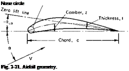 |
Briefly, this section characterizes an airfoil and describes how the aerodynamic forces and moments can be expected to vary with airfoil geometry and Reynolds and Mach numbers. A typical airfoil is shown in Fig. 2-21. Its thickness is the distance between the upper and lower surfaces, and the camber line is defined as lying halfway between them. The chord line is the straight line joining the end points of the camber line. The angle of attack of the airfoil is the angle between the free-stream velocity and the chord line. The zero lift line is an imaginary line passing through the trailing edge; if the airfoil is at an angle of attack a^, so that the zero lift line is parallel to the velocity vector, the lift of the airfoil is zero. This line can be approxi
mated as passing through the trailing edge and the camber line at midchord. The nose circle is centered on the tangent to the camber line at the leading edge. Its radius depends on maximum thickness and airfoil family. Within a given family, airfoils are generated by combining different amounts of maximum thickness and camber. Different families are distinguished by different distributions of thickness and camber with distance along the chord. Earlier families of airfoils had their maximum thickness and camber points about one quarter or one third of the way back from the nose, whereas in later families these points are at about the midchord point.
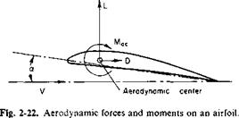
The aerodynamic forces and moment on an airfoil are shown in Fig. 2-22. It is convenient to consider that the lift and drag are acting at a point on the airfoil called the aerodynamic center with an aerodynamic moment Mac about this point. Observe that L and D are defined as perpendicular and parallel to V and that Mac is defined positively nose-upward. The aerodynamic center is a point on the airfoil at which the moment remains constant, independent of a. In Chapter 3 this point is predicted to be at a
 |
||
quarter of the chord from the leading edge. Experimentally, the aerodynamic center usually lies within 1 or 2% of this location; L, D, and Mac are normally presented in dimensionless forms as lift, drag, and moment coefficients.
 |
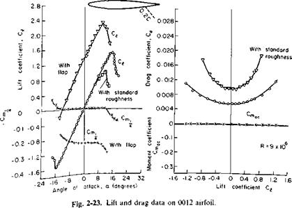
C( increases linearly with a up to a maximum value, C, mai; Cd increases
approximately with the square of a up to C, max; Cm>c by definition of the aerodynamic center, remains constant.
Experimental data on a 0012 airfoil section with and without a split flap is presented in Fig. 2-23. The 0012 airfoil is a 12% thick, symmetrical airfoil (no camber) commonly used on helicopter rotors. Notice that the aerodynamic center of this section is exactly at the quarter-chord point and that the Cmac is zero. Notice also the significant effect that surface roughness has on both C, and Cd , , the minimum value of Cd. The slope of the lift curve has a value of about 0.1 C,/deg, which is representative of most airfoils and a convenient number to remember.
For comparison purposes data on one of the “laminar flow” airfoils, 66-212, are presented in Fig. 2-24. Here the aerodynamic center is slightly behind the quarter-chord point. Because the airfoil is cambered, Cmac is not zero but has a negative value, which means that the nose tends to pitch downward. Also, because of the camber, the angle of zero lift is about —1.5°.
Notice the odd behavior of the drag curve for lift coefficient values between 0 and 0.4. In this region, called the “drag bucket,” the drag is very low, because the chordwise pressure distribution over this limited range is conducive to maintaining a laminar boundary layer that results in reduced
![]()
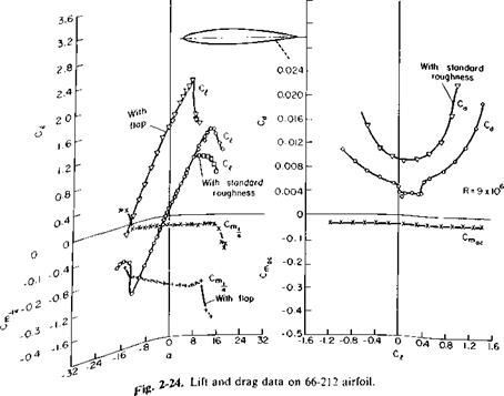
skin-friction drag. Unfortunately, in practice the slightest roughness that might be caused by bugs or imperfections in the contour is enough to trip the boundary layer and produce the usual turbulent skin-friction drag.


