Far-field effect of thickness
 |
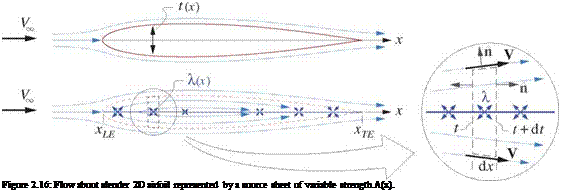
Using a simplification of the models presented in Appendix D, the flow about a non-lifting thin airfoil of thickness distribution t(x) can be represented by superimposing the freestream with a source sheet on the chord line, as shown in Figure 2.16. The required sheet strength X(x) is determined by mass conservation applied to the local control volume.
The total velocity is required to be tangent to the top and bottom of the control volume, since that lies on the airfoil surface. Using the 2D version of result (2.39), the net outflow from the source sheet inside the control volume is therefore equal to the volume flow difference between the left and right faces of height t and t+dt. This gives the required source sheet strength distribution.
A dx = V■ n dl = Vco(t+dt) — V» t = V» dt
![]() dt
dt
A(.t) — 14 ~r~ dx
This is the same as result D.17) obtained for the general airfoil case, so the assumption of a non-lifting airfoil is justified here. The source sheet extends over xLE … xTE (rather than say 0… c) since x = 0 is the chosen location where the far-field singularities are to be placed, as indicated in Figure 2.15. This is not necessarily the leading edge.
From the Kx definition (2.82), with 7 = 0 for this case, we have
/■XTE Г XTE dt
k, x = —Xx dж = Ко / — — x da: (2.87)
xLE xLE dx
 |
|||
where x has been used for both the sheet geometry x’ and the integration coordinate s. The last integral above can be integrated by parts.
The first term on the right vanishes since t(xLE) = t(xTE) = 0 at the leading and trailing edges, and the rightmost integral is the airfoil area A = t dx. This gives a simple result for the x doublet strength.
Kx = VV A (2.88)
This result is strictly valid only if the airfoil is thin, which is required for accuracy of the source sheet model. For airfoils of moderate thickness, a better empirical estimate is
 1 + (2.89)
where tmax is the maximum airfoil thickness and c = xTE – xLE is the airfoil chord.


