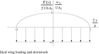
Induced Drag for Non-ideal Wings
For non-ideal wings, let 6 be the relative drag increase compared to the ideal wing, i. e.
![]()
![]() (6.52)
(6.52)
With this notation, the induced drag reads
C2
CDl = nARA(1 + 6) = (Cdi)elliptic (1 + 6) = nR(1 + 6) (6.53)
The wing efficiency parameter is defined as e = 1/(1 + 6) so that, in terms of e the induced drag becomes
![]()
![]()
 |
C2
CL
neAR
6.7.1 Wing Lift Curve and Drag Polar
 |
||||||
The relation CL (a) is now derived for a non-ideal wing. Let a be the geometric incidence for short. Starting from the formula for the lift coefficient in which the circulation has been replaced by the right-hand-side of Prandtl integro-differential equation, one obtains
where
Now, define averaging quantities with the wing area S such as
The value of t ranges between 0.05 and 0.25 according to Glauert [3], for nonideal wings. Often t will be neglected. Upon elimination of A1 this leads to
Finally, solving for Cl
![]() Cl(a) = 2(1+t) (a — a0)
Cl(a) = 2(1+t) (a — a0)
1 + AR~
This result is remarkable in that it gives the lift slope for a finite wing in terms of the aspect ratio
![]() (6.60)
(6.60)
In the limit of very large aspect ratio, the 2-D result of thin airfoil theory is recovered. Furthermore, a0 can be interpreted as the incidence of zero lift for the finite wing. Note that, as was the case for thin airfoil theory, this linear model does not provide a maximum lift coefficient as the full potential equation would. The lift curve is a straight line, but good agreement with real flow lift coefficient will be obtained for small angles of incidence. If a viscous drag coefficient is added to the induced drag, using, say, a flat plate formula based on the wing Reynolds number and the wetted area, an approximation to the wing polar can be constructed as
Assuming a constant Reynolds number, the polars are parabolas. The wing lift curves and polars are shown for different aspect ratios in Fig. 6.19.


