Overall thrust forces
3.5 The general principles of the production of a propulsive force in aeronautical engineering are easily understood and can be described almost in a nutshell. Imagine a man in a vehicle which he wishes to propel forward. Without using reaction forces obtained by direct contact with the ground, he can either throw backward masses which are stored in his vehicle or seize masses from his surroundings (such as water, by means of oars) and set them in motion backwards. In either case, he will utilise as his propulsive force the force of reaction associated with the change of momentum of the masses. The first method is the basis of rocket propulsion, which we shall not discuss here; the second method is the basis of airbreathing propulsion: an aircraft draws air from the relative wind, supplies it with energy, and then discharges it backwards with increased velocity in a jet.
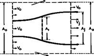
To determine the thrust force of an isolated engine, i. e. the force component on it in the direction of motion, we can apply the momentum theorem to the force and momentum components in that direction. In principle, (3.2) applies. To see the essentials of the flow clearly, we can think of the engine as being a disc of area, situated at the origin*’, at which the energy of the air that flows through it is changed. We want to consider only the changes in the x-direction, and the velocity components other than those in the direction of the mainstream are ignored. We assume that no mass is added during the change of energy. The type of flow to be considered is sketched in Fig. 3.13 (as it is drawn, the thrust would be negative!). The velocity of the air which passes through the engine is Vq far ahead and V – far behind in the Trefftz plane at x = “. Mass flow PqVqAq per unit time enters the control surface through the upstream face with the velocity Vq and entering momentum PqVqAqVq.
^In this coordinate system fixed in the disc, the thrust Th does not perform any work. This is permissible, however, since, when the need arises, we know that, in a coordinate system fixed in space, the propulsive work per unit time is Th x Vq.
The leaving momentum of the mass pjV•A. in the jet is p-V-AjVj and that of the air which leaves the control surface through the area JAq-A- in the Trefftz plane is Po^o^O “ Aj)Vq • This assumes that the energy addition
|
Fig. 3.13 Flow and control surface around a disc where energy is changed |
leaves no permanent changes in the outer stream (such as shockwaves), which is not always true, as we shall see later. There is a further contribution to the momentum changes from the air which is pushed out of the sidepanels due to the expanding flow within the cylinder (in a case like that drawn in Fig.3.13). By continuity, the mass flow per unit time, which leaves in this way, must be (p0V0 – pjVj)Aj. We may assume the diameter of the cylinder to be so large that the axial component of the fluid velocity at its surface is Vq; then the third term corresponding to the momentum leaving the cylinder is (p 0V0 – PjVj> xAjVq. Thus the whole rate of change of momentum and hence the thrust force is
Th = PjVjA^Vj – VQ) , (3.50)
observing that pjVjAj = P]V]A]_. (3.50) states that a positive thrust is pro
duced when a true jet with V – > Vg is formed. The result can be put simply: the thrust is equal to the increase of momentum of the air which passes through the engine per unit time. It also means that, in whatever form energy is supplied, it must in the end be transformed into mechanical work.
A true jet can occur only if the kinetic energy of the jet is higher than that of the air outside it. To achieve this, energy must be supplied to the jetstream from the surroundings and work must be done on it. Therefore, we must look into the question of how this can be done in flouring media. Energy is usually supplied in the form of heat, and the production of meohanioal work out of a supply of heat is the main purpose of a propulsion device. There are two possible ways in which work can be done continuously by changing the state of the medium: (1) The same medium is made to undergo the same changes of state periodically; the medium goes through a olosed oyole and always returns to the initial state. (2) Successive quantities of the medium are made to undergo the same changes one after another, as in steady flow processes; this may be called an open flow oyole or flow process. The latter case is our main concern here (the treatment presented here follows closely that by D KUchemann & J Weber (1953) and (1966); further details can be found there; for a fundamental treatment of technical thermodynamics and its applications see e. g. E Schmidt et al. (1975)).


