Prandtl Lifting Line Theory (Incompressible Flow)
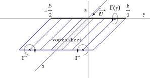
In incompressible flow, for large aspect ratio wings, i. e. AR > 7, Prandtl [2] imagined the following model for the flow, shown in Fig. 6.15.
The flow is described as a lifting line and a semi-infinite vortex sheet, made of vortex filaments which run from x = —ж to x = 0, turn abruptly along the y-axis and turn again to leave toward the Trefftz plane. The wing of Fig. 6.7b has been collapsed along the y-axis, between – b/2 and b/2. The circulation Г(y) fully describes the vorticity content of the flow, i. e. the bound vorticity inside the wing, as well as the trailed vorticity, Г'(y), of the vortex sheet. The circulation Г(y) is found by matching the local flow incidence with the profile characteristics at a given wing cross-section y, as if in isolation or part of an infinite wing. This is the so-called strip theory, which has proved useful for slender lifting elements such as large aspect ratio wings, helicopter and wind turbine blades. Mathematically, this corresponds to neglecting the derivatives along the span in comparison to the other derivatives, in other words, д/дy ^ d/dx, d/dz.
On a more historical note, Prandtl initially thought of representing the flow vor – ticity with a single horseshoe vortex of finite intensity corresponding approximately to the maximum circulation in the wing. However, he soon realized that the induced drag of a finite vortex is infinite because the azimuthal velocity component varies as 1 /r, where r is the distance from the vortex center, so that v2 + w2 a 1 /r2, which in the Trefftz plane integrates as ln r, a diverging integral over the vortex, yielding an infinite drag.
Lets assume that the profiles that equip the wing are characterized by their 2-D lift coefficients Ci(a), known from thin airfoil theory, say C;(a) = 2n(a — a0), where a0(y) = —2d(y)/c(y) represents the incidence of zero lift and d(y)/c(y) is the relative camber. The setting angle or twist of the wing, t(y), is an additional geometric parameter. Note, that, without restriction, one can set t(0) = 0 for a symmetric wing. Negative values of t(y) or nose down toward the wing tips is called washout, whereas positive values or nose up is called washin. Figure 6.16 depicts the local working condition of the profile in the y = const. plane.
|
Fig. 6.15 Prandtl model for large aspect ratio wing |
q
Fig. 6.16 Matching of local incidence and local lift coefficient
The profile setting angle with respect to the x-axis is given by ageo +t(y), where ageo corresponds to the geometric incidence given to the wing. The effective incidence of the profile is aef = ageo +1 + ai, where we have accounted for the induced incidence. The local lift coefficient is therefore
Ci(y) = 2n ^aeffiy) + 2 y^ = 2n ^ageo + t(y) + 2cy) + ai(y)^
![]()
= 2n (ageo – a0(y) + ai(y))
For the wing with twist, a0 = -(t + 2d/c). The relation between the circulation and the local lift coefficient, as seen before, is
2Г( y)
Ci (y) = (6.40)
Uc(y)
Here, we have replaced q with U since ai = ww /U is small. Substitution of the local lift coefficient in terms of the circulation and of the formula for the downwash at the lifting line, yields the integro-differential equation of Prandtl
Two types of problems are commonly considered: the analysis and the design problems. In the analysis problem, the wing geometry is given, that is c(y) and a0(y) are known. The objective is to find the circulation Г, the lift and the induced drag for different values of the geometric incidence ageo. In general, this problem does not have an analytical solution and can only be solved numerically. This is particularly true if the planform has kinks as in the case of the trapezoidal wing. The numerical approach will be described later.
As a designer, one can study the properties of a wing having a given loading, Г(y), and relate the loading with the induced drag in order to obtain the minimum drag for a given lift. It will remain to find how to build such a wing. In this inverse approach, as was done in thin airfoil theory, the circulation is represented as a Fourier series of sines, after a change of variables from y to t
An sin nt
![]()
 |
n=1
y(t) = —b cos t
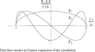
Note that, unlike in thin airfoil theory, the series contains only regular terms that satisfy the boundary conditions at the wing tips Г(0) = Г(п) = 0. Note also that the development is for Г not Г’. The first three modes Гп(y) are shown in Fig. 6.17.
It can be seen that the even modes are antisymmetrical and will induce a rolling motion to the wing. In symmetrical flight, only the odd modes are present in the solution.
Substitution of the Fourier series in the formula for the lift coefficient along with the change of variable yields
^ п b 2 Г 2 2
Are/Cb = 4b An sin nt sin tdt = 2b2A1 sin2 tdt = nb2A1 (6.43)
n=1 J° 2 J°
where we have exchanged integration and summation, and used the orthogonality of the Fourier modes. If we choose as reference area the wing area, i. e. Are/ = S, then the result is
Cl = nARA1 (6.44)
The lift depends on the first mode only.
The induced drag is now considered. First, one evaluates the downwash in the Trefftz plane by substituting the Fourier expansion in the formula for wT to get with П = cos в
where again, integration and summation are switched, and the result, taken as principal value integral, can be found in books of integrals.
 |
|
The expression for wT can now be inserted in the formula for the induced drag as
where we have use orthogonality of the Fourier modes, term by term, from the product of the two series. Let Aref = S, then the result reads
O
CDi = nAR^ nA2n (6.47)
n= 1
 |
This result proves that the induced drag is zero only if all the coefficients are zero, that is if Г(y) = 0. This is the case with a flat plate wing at zero incidence. For a given, non-zero lift, A1 = 0, the minimum drag is obtained when A2 = A3 = ••• = An = ••• = 0, n > 2. Such an ideal wing has a circulation distribution given by


