Reverse Flow
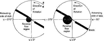
At higher rotor advance ratios, a considerable amount of reverse flow will exist on the retreating side of the rotor disk, that is, the blade sections operate with the trailing edge into the relative wind. This reverse flow region on the rotor disk is illustrated by Fig. 5.9. The locus of the region where Uj — 0 means that
UT = 0 = QR(r + fjismf), (5.41)
which has the simple solution r = —д sin j/. Therefore, the region of reverse flow where Ut < 0 covers a circular region of the disk of diameter д, with the circle centered at
(r, Jr) = (p/2, 270°). In this reverse flow region the sign of both Ut and the sectional drag contribution to the rotor drag changes (see Section 7.11.6), and so this must be accounted for in the radial and azimuthal integration to find the rotor power and drag coefficients. For a conventional helicopter the maximum feasible advance ratio is about 0.5, which means that the inboard 50% of the retreating blade operates in reverse flow. Autogiros, however, may operate at much higher p – see Chapter 12.
The effects of reverse flow can be included by changing the sign of the drag in the region defined by r = —p sin Jr on the retreating side of the disk. This may be treated by writing the integral in the profile power equation as the sum of two parts, that is
р2л /*1
Cp0 = —2— / / (r + p sin if )3dr d Jr
4tt Jo Jq

 |
— 2л p —/X sin yj/
I (r + psinir)3dr djr, (5.42)
Jo
where the first integral has been previously evaluated in Eq. 5.28 and the second integral is the increment that accounts for the proper sign on the drag inside the reverse flow region (see Question 5.4). If the drag coefficient is assumed to be unchanged in the reverse flow region, then after integration the profile power coefficient becomes
Cp0 = —^ Л + 3p2 – f • (5.43)
This result is a fairly common approximation that can be used in a rotor performance analysis
o«H T7trr ^ cimerarfn itr iruli/lift/ to ллаЯ frv uk/міі n П Л Flrxiiklinrr fko Hrorr nmnt
uuu x ig. no vanunj io guuu iu auuui fob — j,-r. lyvuuun^ uiv uiug wwinvivuv
in the reverse flow region (see results in Section 7.11.6) will increase the coefficient of the p4 term to 3/4. The equivalent rotor drag force coefficient corresponding to Eq. 5.43 is
when including reverse flow. When radial flow is included then
![]() cPo = 2|*( i+V)
cPo = 2|*( i+V)
and with radial and reverse flow then
Cpa = (1 + V + • (5.46)
Harris (1966) and Johnson (1980) summarize how various other assumptions affect the profile power, including the effects of reverse flow and modified drag coefficients in yawed and reverse flow. The validity of some of these assumptions, however, are questionable at higher advance ratios and larger advancing tip Mach numbers and do not necessarily lead to more accurate models of the profile power. For example, because the blade stalls in the reverse flow region, the assumption that Cj = Cd0 (or even Cd = constant) is clearly invalid there (see Section 7.11.6). Generally, however, the effects of the various other assumptions are small, except for radial flow and drag effects in yawed flow, which Johnson (1980) suggests must be included to give an accurate calculation of rotor power. In this case numerical evaluation of the blade element integral is required. But the main advantage of this numerical approach is that more realistic models of the airfoil drag as a function of angle of attack (AoA), including stall, dynamic stall, yawed and radial flow, and compressibility effects can be included into the rotor performance predictions.


