Speed for Maximum Range
The range of the helicopter is the distance it can fly for a given takeoff weight and for a given amount of fuel. In all cases contingency fuel allowances (i. e., reserves) must be
1Г4ІЛ ПЛЛЛППІ /4 /4 1ПГТ ЛП fU Л ПГЧЛП Л ГИЛ/4 AfV* /-»** ЇМПИПІ Г-Ч-** і rt nffl 1 tv« Я ч rrVif
uitvs attuuiu, uv^j^iuauig un uit* uuddiuu piunio anu wii^ux^i visual ui uiduuuiciu infill
rules apply. The range can be written as R = V t so in terms of SFC and a given amount of fuel, a first approximation to the range is
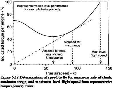
Typically, the fuel burn versus airspeed curves mimic the power required curves if the engines operate at the power settings where their SFC curves are relatively flat, as shown in Figs. 5.15 and 5.16. Therefore, as a first approximation the speed to fly to give the best range is obtained when the ratio V/P is a maximum or the ratio P/V is a minimum, that is, when the helicopter is operated at the best lift-to-drag ratio. For no-wind conditions this speed is graphically obtained from a line drawn through the origin and tangent to the P versus V (or torque versus V) curve, as shown in Fig. 5.17. As can be seen that this airspeed is usually at a somewhat higher airspeed than that required for maximum endurance. Notice that this speed will change with both the weight of the helicopter and with the atmospheric conditions.
 |
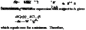
The speed to fly for maximum range, Vmr, is also determined essentially by the variation in induced power and the parasitic power. Therefore, the ratio of P/V can be approximated
 |
|
by the expression
Note that, like the speed for maximum range, this speed will also increase with increasing density altitude and with the square-root of aircraft weight.
 |
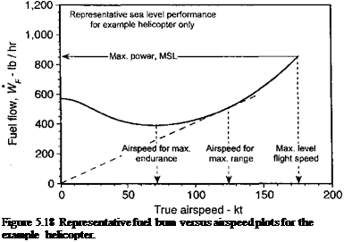
A more accurate estimate of range will take into account the actual SFC curves and fuel flow rates at the particular power settings for the altitude and temperature at which the helicopter is actually flying. From the representative results shown in Fig. 5.18, it is apparent that the maximum range condition that P/V is a minimum is obtained when a line drawn from the origin of the axes is tangent to the fuel flow curve. The resulting fuel flows (in units of lb hr-1 or kg hr-1) for different conditions (see Fig. 5.16) can then be used to find the specific range (in terms of distance flown per unit of fuel). Such results would normally be plotted as specific range versus true airspeed for different density altitudes. Determination of maximum endurance (see Section 5.20) also requires an accurate determination of the fuel flow curves.


