STALLING OF STRAIGHT WINGS
The stalling of a wing occurs when the more or less linear function of lift with angle of attack comes ultimately to an end. At this angle where the lift is no longer linear, the flow of the air separates from the suction side and the wing stalls. The stalling of a three dimensional wing is dependent on all the factors discussed in this chapter including the section shape, angle of attack, Reynolds number, Mach number and the planform shape. The stalling of the wing is dependent on the local angle of attack of the sections as effected by both geometrical and induced flow characteristics. Thus, the aspect ratio and shape of the planform are of primary importance. The stalling characteristics of low aspect ratio, delta, and swept wings are complex and, therefore, are covered in separate chapters.
Plan Form. As mentioned in Chapter III, the local lift coefficient of a rectangular wing is highest at the center; stalling, therefore, begins here. On the other hand, in a highly tapered wing, stalling is bound to start at and near the wing tips. Since it is desirable to have a wing display a gradual stall and maintain lateral control, a wing that stalls inboard first is desired. For this reason, reduction of wing-tip stalling is often attempted by twisting the wing so that the effective angle of attack is smaller at the tip than the root. This procedure (“washout”) is often supplemented by the use of slots, etc., see Chapter VIII.
|
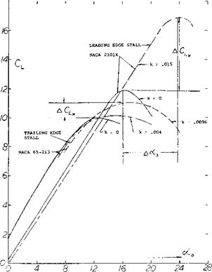
Figure 38. Lift coefficient and angle of attack overshoot from static stall due to dynamic effects (32,d). |
M0 = .23, Rc = 6.9(10)6 NACA 23016 ROOT NACA 23009 TIP A = 6
TAPER RATIO = 2:1 SMOOTH ‘
WASHOUT = 4°
TN – 1299
A typical flow pattern for a tapered wing showing the progression of stall with increasing angle is shown on figure 39. It will be noted that the aspect ratio 6 wing using NACA 23 xxx series airfoils (33,a) develops stall near the trailing edge, and that there is a cross flow from the wing tip. Also, after the maximum lift coefficient has been exceeded the wing tips are still not completely stalled. For the aspect ratio 10 wing with the same type of sections (33,b) stall proceeds in the same manner as the AR = 6 wing. The stall pattern shown would be expected since both wings are built with the tips washed out to obtain this pattern.
In both cases the wings with NACA 23 xxx section exhibited an abrupt stall even though the stall appears to start at the trailing edge. Sharp stall would not be predicted from figure 8, but appears to be a characteristic of the 23 xxx airfoils and is seen in the two dimensional airfoil data (1 l, b). For wings using NACA 64 and the four digit series the stall is more gradual and of the type that would be predicted using figure 8. The prediction of these characteristics of plane wings is accurate using two – dimensional airfoil data for the proper operating condition of Mach number and Reynolds number and the lifting line theory (30).
(33) Straight & Taper Wing Stall:
a) Mach and Reynolds No. Effects, NACA TN 1299.
b) High-Aspect-Ratio Tapered Wings, NACA TN 1677.
c) Compressibility Effects, NACA TN 1877.
d) Tapered Wings, NACA WR L-311.
(34) Influence of surface roughness on maximum lift:
a) Williams, Thick Sections in CAT, ARC RM 2457 (1951).
b) Hoerner, Survey, Ringbuc|t. vLufo Rpt IA9 (1937).
c) Jones, 0012 and RAF-34 in CAT, ARC RM 1708 (1936).
d) AVA Gottingen, Ergebnisse III*(1927) p 112.
e) Hooker, Airfoils w’Roughness, NACA TN 457 (1933). 0 See also references under (28).
(35) Characteristics of sharp-nosed sections:
a) Daley, 6% Thick Sections, NACA TN 3424 (1955).
b) DVL, Double-Arc Sections, see (8,c) or (19).
c) Solomon, Double Wedge, NACA RM A6G24.
d) Polhamus, Drag Due to Lift, NACA TN 3324 (1955).


