The Working Fluid
The volume of air in which the propeller works is the working fluid, and is described as an inviscid fluid flow. The term inviscid describes the air flow and assumes it to be one without viscosity, or devoid of any internal friction or drag force. The airflow approaching the prop is termed the relative air flow (RAF) and shown by three arrow heads on the diagrams; it is also known as the inflow velocity. The air flow behind the prop is termed the propwash or outflow.

|
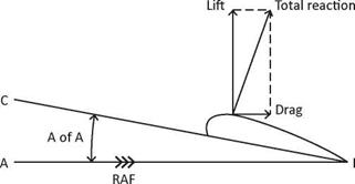
All pilots should be familiar with the diagram below, Diagram 1, Airfoil Terminology, from their previous study of classical aerodynamics. The diagram depicts the terminology used in defining the wing’s airfoil section, chord, relative airflow, angle of attack, lift, drag and total reaction.
|
Diagram 1, Airfoil Terminology |
Briefly, the line A-B represents the path the airfoil is moving along. The relative airflow is therefore moving along the same path, but in the opposite direction and depicted by the three arrow heads. The line C-B represents the extended chord line and the direction the airfoil is pointing. The angle between A-B and C-B, that is, between the relative airflow and the chord line, is the angle of attack. Due to the angle of attack, the air mass flowing over the airfoil will produce an aerodynamic reaction known as the total reaction (TR), which can be divided into the forces of lift and drag The propeller is a rotating wing and shares the same terminology as the aircraft’s wing. Because the prop is rotating around its axis combined with the forward motion of the aircraft, it requires additional vectors and terminology to fully describe it, as follows:
• The chord line is taken to be a tangent to the lower surface of the prop blade.
• The blade element is a theoretically thin cross section of the prop blade (it is the counterpart of the wing’s airfoil section) and is perpendicular to the blade’s major axis. The blade profile is the shape of this cross section of the blade.
• Confusing as it may sound, the propeller’s back is the curved, upper surface and this part of the prop is viewed from in front of the aircraft.
• The prop blade’s relatively flat surface corresponds to the wing’s under surface and is known as the prop blade’s face, thrust face or pressure face due to this side of the propeller producing air pressure above ambient, but more of this later in ‘Propwash Thrust’. The face is usually painted a matt black to reduce reflection making it easier for the pilot to see through the prop disc in flight.
• The shank is located at the blade root and being circular; it is not an aerodynamic shape and therefore plays no part in producing thrust, although it does produce some drag. Not all propellers have shanks.
• The propeller’s boss is the thick central non-aerodynamic part of a wooden fixed-pitch prop.
• The hub is in the same central position as the boss but is a separate unit to which the blades and constant-speed unit are attached
• The spinner is the streamline fairing covering the hub area. On some aircraft it is used for aesthetic reasons or it may also be an essential item on other aircraft to smooth the airflow into the engine air intakes, and reduce drag.
• The prop blade’s leading and trailing edges, plus the tips and roots, all share the same terminology as applied to an aircraft wing.
The blade cuff is located at the blade root to enhance air flow into the engine intakes and for greater propeller solidity.
|
Diagram 2, Propeller Terminology |
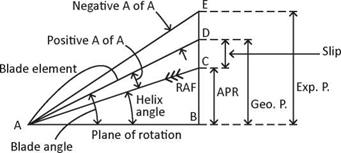
Comparing Diagram 2, Propeller Terminology with Diagram 1, it is shown the blade element, chord line, relative airflow and angle of attack are all shown similarly, albeit reversed [Classical aerodynamic diagrams by convention are shown as moving from right to left, and the reverse direction for propeller aerodynamic diagrams]. Diagram 2, also shows the relationship of the helix angle AB-AC, the blade angle AB – AD, the angle of attack (AC-AD), all measured in degrees. The advance per rev (B-C), the geometric pitch (B-D), the slip (C-D) and the experimental pitch (B-E) are all measured in inches; vector B-E represents the prop’s axial (or forward) component. Using a breakdown of Diagram 2, each factor can now be examined in more detail, keeping the following points in mind All that follows will also apply to a constant-speed propeller; however, it will be assumed for now a given blade section on a fixed-pitch propeller is being considered where the geometric pitch and experimental pitch both remain constant and the advance per rev and slip are variables Also, vector A-B represents the tangential component or plane of prop rotation
What is the definition of pitch? And what is the difference between the experimental pitch, the geometric pitch and the advance per rev? The difference will be revealed as each term is considered in turn.
The definition of the term ‘pitch’ and its analogy with the common screw must be defined. When a screw is screwed into a solid medium such as wood, it will advance a given distance in each turn equal to its pitch; in other words, its advance per revolution is a fixed quantity equal to its pitch. The geometric pitch of the screw is the distance between each adjacent thread
When an aircraft is gliding with the engine/prop stopped, the propeller’s advance per rev is infinite, as opposed to a stationary aircraft with the engine running and the prop’s advance per rev is zero The advance per rev of the propeller is a variable quantity depending on the aircraft’s speed, and propeller RPM, or lack of either, between these two extremes.
Some text books state the analogy with the wood screw is useless, because the screws advance per rev is a fixed quantity, while the props advance per rev is a variable quantity between zero and infinity. That is true, but there has to be a condition of propeller operation somewhere between these two extremes that satisfies the definition of geometric pitch. And there is! When the aircraft reaches a given forward speed, the propeller blade’s angle of attack will become zero and the advance per rev will equal the geometric pitch, which is exactly what happens with a wood screw
In conclusion, two things have been proven, one, the screw analogy is a true and useful example to introduce the definition of pitch, and two, under certain operating conditions of aircraft forward speed and prop RPM, the advance pre rev equals the geometric pitch
The helix angle (AB-AC) which is also known as the angle of advance, is the angle between the propeller’s plane of rotation (A-B) and the resultant direction of the relative airflow (RAF), vector A-C in Diagram 2.
When the engine is running the prop will have a rotational velocity, vector (A-B) in Diagram 2, and will travel on a circumferential distance equal to 2nR in unit time in the plane of rotation. The rotational velocity is also known as the tangential velocity. When the aircraft is moving forward, it will have a forward velocity along the axial vector component (B-C) and it will cover a given forward distance known as the ‘advance per rev’ (or the effective pitch) in unit time depending on the forward speed of the aircraft. Any change in prop RPM or advance per rev will induce a change in the helix angle (AB-AC). The helical flight path followed by the chosen blade element will be along the vector A-C. The helix angle is related to the advance per rev, or effective pitch (B-C).
The helix angle can be found from the following formula:
P
Helix angle, tan 0 = „ „
2nR
Where P = B-C axial component or effective pitch (APR)
R = prop radius n = 3.14…
Therefore, the effective pitch can be found from the formula:
Effective pitch (P) = 2nR tan 0
The propeller tip’s helical path will be approximately 45° from the vertical and increases towards the blade root The blade tip helix angle will also vary from zero degrees when the aircraft is stationary through approximately 45° at the design cruise speed, to a greater angle as the aircraft’s speed increases above its design cruise speed.
The blade angle is defined as the angle between the propeller’s plane of rotation (A-B) on Diagram 2, Propeller Terminology, and the prop blade’s chord line (A-D) combing the helix angle plus the angle of attack. It has the same meaning as a wing’s angle of attack.
Each blade element travels on a different helical path and to produce the maximum lift/drag ratio must meet the relative airflow at the same small angle of attack of 3-4°. To achieve this constant angle of attack, along the length of the blade, the propeller blade must be twisted. This is known as the propeller’s geometric twist where the angle between the blade chord and its plane of rotation varies along the blade’s length. This requires the blade angle to be greater at the root with a gradual reduction towards the tip, as mentioned above. The geometric pitch of the propeller then remains constant (geometric pitch = 2nR tan 0) due to the blade angle decreasing with an increase in blade radius. The actual blade twist is designed to provide the correct angle of attack at the design cruise speed.
Although the blade twist is associated with the geometric pitch, it must not be confused with the definition for blade angle and pitch. The blade angle is measured in degrees between the vectors A-B and A-D, while the pitch is measured as a length in inches (or centimetres) along the vector B-D.


