Trailing Edge Blowing System
The TEB design was developed from a series of experiments in a small transonic blowdown wind tunnel at Virginia Tech. Steady velocity field measurements were taken downstream of the WG to assess the infhence of discrete TEB hole size, shape, and pitchwise spacing on the wake-filling effectiveness. The tests were conducted at an inlet Mach number of 0.6. These experiments confirmed the feasibility of TEB at high subsonic speeds and close axial distances, and led to selection of a final TEB hole configuration for the subsequent compressor rig experiments.
In order to minimize unsteady rotor blade loading, it is desirable to promote as much circumferential fbwfield uniformity as possible. As such it was deemed unnecessary, even undesirable, to place TEB holes within the endwall boundary layers, which are present for the entire circumference. The selected TEB design consisted of seven blowing holes per WG, with both TE thickness – to-diameter and hole pitch-to-diameter ratios of 2.5, which provided effective coverage for almost the entire span between the endwall boundary layers.
|
Figure 2. Detail of SMI rig showing approximate strain gauge locations and trailing edge blowing configuration. |
While complete wake-filling would maximize circumferential flowfield uniformity, the compressor bleed air requirement to achieve this may be prohibitively costly to overall engine performance. It was desired to characterize the sensitivity of the forced response to the flowrate of TEB air and its span – wise distribution. Thus the TEB plumbing was designed to permit independent adjustment of flow to different spanwise sectors of holes. As shown in Fig. 5, four independent lines supplied the seven holes. One supply line fed a single tip hole, while the remaining three lines each supplied a pair of TEB holes. Maximum flow variation between paired holes was estimated to be 5%.
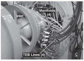
Because the single-stage compressor rig did not have sufficient pressure ratio to feed the flow control system by bleed recirculation, high-pressure air was supplied for TEB from external storage tanks. The flow was throttled to a typical settling tank pressure of 100 psi (690 kPa) and then independently regulated to four rig-mounted plenums, as shown in Fig. 5. Each plenum, with a typical pressure of 60 psig (414 kPa), distributed fbw evenly to the same radial sector of TEB holes of all 12 WGs. Because the plumbing was designed for installation ease and experimental flexibility rather than for minimizing pressure losses, it should be noted that this high TEB supply pressure is not representative of requirements for engine implementation. A pressure ratio of 2-3, typically achieved within two high-speed stages, should be adequate for implementing an efficient TEB design.
|
Figure 3. SMI rig assembly with TEB manifolds and tubing installed |


