Aerodynamics of the wing
The theory of finite wings is well known. Developments based on lifting line theory can be found in many texts [1, 2] and several treatments of lifting surface theory may be considered classic [3, 4, 5]. A basic assumption in all of these presentations is that the trailing vortex system is aligned with the free-stream velocity. For the usual lift coefficients such an assumption is valid. However, for V/STOL aircraft that employ extreme methods of developing high lift the assumption must be re-examined. This chapter, therefore, treats the finite wing, with the deflection of the vortex system being considered. Such a consideration leads to several important differences between the linearized theory and the more exact treatment.
Two-Dimensional Airfoil Theory
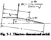
Before we examine the general treatment of finite wings, the theory of thin, two-dimensional airfoils will be developed. An understanding of two – dimensional airfoil theory is necessary to the study of finite wings. Consider the two-dimensional thin airfoil shown in Fig. 3-1. The problem in predicting the potential flow about this airfoil is that of finding the functions ф and ф, which, in addition to being harmonic, will satisfy the boundary condition that the velocity normal to the airfoil be zero. In the solution of this problem one method consists of distributing point vortices along the mean camber line and adjusting their strengths to induce velocities which, when added vectorially to the free-stream velocity, produce velocities tangential to the mean camber line. These vortices are distributed in a continuous manner by defining a strength у per unit length such that the strength of a differential point vortex is у dx. Because the maximum camber is usually small in comparison with the chord (less than 4%), the problem can be linearized by placing the distribution of у along the chord line and calculating the induced velocities there also.
A vortex of strength у dx placed at x will induce an upward velocity at A’o given by
To find the total velocity induced at x0 (3-1) is integrated over the chord.
![]() y(x) dx x — x0
y(x) dx x — x0
The angle formed by this velocity and the free-stream velocity defines the local direction of the mean camber line of the airfoil at x0.
 |
If z is the upward displacement of the airfoil from a reference chord line
at an angle of attack a to the velocity V, then to a small angle approximation
Thus we should be able to specify a y(x (-distribution and find by (3-2) and (3-3) the shape of the mean camber line and a to produce such a distribution.
There is one restriction on the choice of а у-distribution. It can be shown that if у does not vanish at the trailing edge of the airfoil r,(c) will be infinite. In order to ensure that r;(c) will be finite so that the flow can leave smoothly and tangentially from the trailing edge, the restriction is placed on у that
y(c) = 0. (3-4)
Equation (3-4) is known as the Kutta condition and is imposed as the result of experimental observations that in a real viscous flow the streamlines are tangent to the mean camber line at the trailing edge.
It is convenient to transform Eq. (3-2) as follows: Let
Without any justification at this point, let us assume that y, now as a function of 0, can be expanded in the form
![]()
![]() " (1 + cos 0) ” ‘
" (1 + cos 0) ” ‘
A°—– ;—a— + Z An Sln пв
sin 0 і
If we use the relationships
![]()
 |
|
j[cos(« — 1)0 — cos(n + 1)0] = sin пв sin 0
Eq. (3-6) becomes
From (3-9) and (3-3) it follows that
Thus from the above it is possible to determine the у-distribution produced by a given airfoil geometry.
 |
Consider now a portion of the vortex distribution shown in Fig. 3-2. If
Av is the velocity induced tangentially just above and below the vortex sheet, then by evaluating the circulation around the differential element we obtain
2Av dx = у dx
or
Ar = (3-11)
If sub и refers to the upper surface and / to the lower surface, then Bernoulli’s equation gives
Po + iPV2 = Pu + ЫУ + Ad)2,
Po + У V2 = pi + – Ad)2,
or
AP = Pi~ pu = pV(2Av) = pVy. (3-12)
The equation relating Дp and у could have been obtained immediately from the Kutta-Joukowski theorem, which states
F = pX x Г. (3-13)
For two-dimensional flow this becomes
L = pVY. (3-14)
Here L is the lift per unit span normal to V which is produced by the
circulation Г. The Kutta-Joukowski theorem can be proved by the application of the momentum theorem and Bernoulli’s equation to a control surface containing one or more vortices with a combined strength of Г.
The lift coefficient of the airfoil is defined as
If у is given, C, can be found immediately. If the camber and angle of attack are given, then C, can be obtained from
A0 and Ax are determined from (3-10).
The moment, positive nose-up, on the airfoil about its leading edge can be determined from
The moment coefficient CmLE is defined by
p ^LE
mLE “ $pV2c2‘
In terms of the expansion for y, CmLE becomes
CmLE = (Л + A, – (3-17)
The moment about any other point on the airfoil is given by
M – MLE + xL
or in coefficient form
Г = Г + – С,
m vmLE 1 ^ /
= —— M0 + Ax————- — J + — (2nA0 + nAt).
The aerodynamic center of an airfoil is defined as the point on the airfoil at which the moment coefficient remains constant, independent of the angle of attack. Such a point can be found by differentiating the above with respect to a and equating it to zero:
dCm = 0 = (n 2яхас dA0 da. I 2 c J da
or from (3-10)
Thus the aerodynamic center, according to thin airfoil theory, is located at the quarter-chord point and is not a function of camber. The moment coefficient about this point is given by
Стао= ~^(Аг – A2). (3-19)
The Circular Arc Airfoil
As an example in the use of thin airfoil theory, consider first the case in which it is desired to produce lift with an airfoil of prescribed pressure distribution. Since Ap is proportional to y, let
У = Ушах sin в. (3-20)
Such a distribution is desirable, for example, from the standpoint of avoiding
compressibility effects in air or cavitation in hydrodynamic applications, for the low-pressure peak associated with the first term in the brackets of Eq. (3-7) is not present.
From (3-2)
V = Ушах p sin2 в dO
! 2n Jo cos в — cos в0
or
/max л
vt = —cos в.
which when substituted into (3-3) leads to
![]() . /max / 4
. /max / 4
“+ 2V11-"
When x = c, z = coc, which means that the trailing edge and leading edge are aligned with the velocity V. Hence a is equal to zero and z will be given by
![]() x(c — x)
x(c — x)
or
where
![]() Ута»С 8F ‘
Ута»С 8F ‘
It can easily be verified, to the approximation that c « R, this is the equation of a circular arc with a radius of curvature given by
![]() R =
R =
or
![]() (3-21)
(3-21)
ymax can be obtained from C,. From (3-15)
2FC,
n
Finally, the radius of curvature and the maximum camber are related to the chord and C, by
|
n c 2 c; |
(3-22) |
|
cC, |
|
|
i An |
(3-23) |
Thus to construct an airfoil with an elliptic chordwise pressure distribution and producing a desired C, it is necessary only to construct a circular arc of radius R and chord c according to (3-22).
In the preceding discussion we have found the airfoil shape required to produce a desired pressure distribution. Now consider the calculation of the pressure or у-distribution produced by a given shape. Let us take as an example the same circular arc airfoil but at an angle of attack a different in general from zero. Again,
X / X
![]()
4- 1 —
![]() – cos в.
– cos в.
Thus from (3-10)
A0 = a,
Л __ ^max
Л1 — 5
![]() Aj — А-ш
Aj — А-ш
so that
and
Several important points may be noted from these results. First, the C, is directly proportional to a and to the ratio zmai/c. Second, the effects of the angle of attack and camber, both on C, and y, can be determined separately
and then simply added together. Also, notice that, for other than a = 0, у becomes infinite at the leading edge. The result is high local velocities in that region.
The Finite Wing
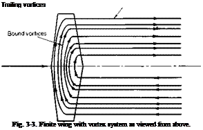 |
A finite wing is shown in Fig. 3-3. The vortex system of this wing is made up of two sets of vortices; bound vortices, which run spanwise and are “bound” to the wing, and trailing vortices, which are shed from the wing and trail downstream. The trailing vortices are a consequence of Helmholtz’s theorem of vortex continuity. Since the lift distribution along the wing must diminish to zero at the wing tips, it follows from the Kutta-Joukowski theorem that the strength of the bound circulation must vary in the span-
wise direction. Hence from vortex continuity this change in the bound circulation must be shed downstream extending to infinity.
The direction of the vortices that constitute the vortex system of the wing are determined according to the right-hand rule. It can be argued from a physical viewpoint that in the vicinity of the tips the air tends to flow from the high-pressure region under the wing outward around the tips and in toward the center of the wing on the upper surface, where the pressure is reduced. Thus the trailing vortices are directed forward on the left side of the wing (looking forward) and aft on the right side. To form a closed system the bound vortices must then be directed from the left side to the right side.
The direction of the bound vortices can also be determined from the Kutta-Joukowski law. To produce a positive lift the circulation around a wing section, when viewed toward the right, must be in the clockwise direction.
As in the two-dimensional airfoil, the strength of the vortex system of the
wing, both bound and trailing vortices, must be adjusted so that the resulting velocities are everywhere tangent to the wing surface.
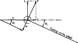
Consider the velocities induced along the chord of a section of the wing by the trailing and bound vortices, shown schematically in Fig. 3-4. Provided the chord of the section is small in comparison with the span of the wing, the velocities induced along the chord by the trailing vortices are nearly constant and directed downward. Thus, the principal effect of the trailing vortices is to redirect the incoming flow downward through some angle to decrease effectively the angle of attack of each section of the wing. The angle through which the flow is directed downward is called the induced angle of attack a,. The velocities induced by the bound vortices, again provided that the chord of the section is small in comparison with

 |
•Velocity due to trailing vortices
the span of the wing, are assumed to be related to the section camber and effective angle of attack in the same manner as the two-dimensional airfoil. Thus, the problem of the finite wing is reduced essentially to that of finding the velocities induced by the trailing vortex system.
The usual model assumed in calculating w, the downwash induced at the wing by the trailing vortex system, consists of a single bound vortex of varying strength Г in the spanwise direction from which is shed the continuous trailing vortex sheet. The downwash is then calculated along the bound vortex line. Such a model is shown in Fig. 3-5.
In determining w, we must be careful of sign convention. The problem is one of integrating differential quantities; hence, in setting up the integration, all differential quantities must be shown generally in a positive sense. If, in going from у to у + dy, the strength of the bound vortex increases from Г to Г + dT, then, from vortex continuity, a trailing vortex of strength dT must be feeding into the bound vortex between у and у + dy. Hence by the use of (2-39), where cos a = 0 and cos /1=1, the differential downwash induced at some other location у must be given by
![]() (3-26)
(3-26)
In a general sense (3-26) is not the downwash but rather the velocity induced normal to the plane in which the trailing vortex sheet lies. If this plane is assumed to be horizontal or, more specifically, parallel to the direction of V, then dw will be the downwash.
The trailing vortex sheet must lie along streamlines; hence, because it induces a velocity approximately normal to itself over its entire surface, the trailing vortex sheet does not trail horizontally from the wing but is deflected downward. Because the induced velocities increase with greater distance behind the wing the deflection of the sheet increases as we move downstream toward an asymptotic value.
 |
Consider for the present the velocity induced according to (3-26) by a flat
Fig. 3-5. Lifting line model of wing vortex system.
vortex sheet whose strength is governed by a bound vortex with an elliptical distribution of Г over the span given by
If a coordinate transformation from у to 0 is made, namely,
![]() (3-28)
(3-28)
(3-27) becomes
Г = Г0 sin в.
The above в should not be confused with the в used in thin, two-dimensional airfoil theory. Equation (3-26) for this case becomes
![]() Г0 f* cos в dO 2nb)0 cos в — cos 0o
Г0 f* cos в dO 2nb)0 cos в — cos 0o
With the aid of (3-8), we find that for the elliptic distribution w is a constant given by
Because w is a constant, the induced angles of attack are constant, so that for an untwisted wing the effective angles of attack of every section are the same.
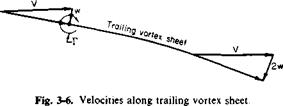 |
Consider now Fig. 3-6, which is the velocity diagram for a section of the wing. In accordance with the lifting line model, the chordwise distribution of у has been collapsed to a point vortex of strength Г. The vortex sheet is shed at some initial angle and curves downward asymptotically toward the angle sin-1(2h,/F). This asymptotic angle results from the fact that in the ultimate wake, in which the trailing vortex sheet extends from — oo to oo, the induced velocity will be twice that given by (3-29).
Because the shape of the vortex sheet and the variation of w in the x-direction are mutually dependent, the exact force system of the wing is most readily obtained by applying the momentum theorem to control surfaces far removed from the wing. This procedure is carried out later. At present, it is instructive to consider an approximate possible limiting case.
We might argue that the induced velocity at the wing is determined mainly by the portions of the vortex filament close behind the wing, for after a time the action of viscosity will dissipate the vortices. Thus one limiting case that might be considered at the wing is shown in Fig. 3-7.
If the section lift is defined as the vertical component of the resultant force on the section, then
L = p(V — w sin <Хі)Г;
but
![]() sin a, =
sin a, =
so that the section Ct becomes
![]() 4b c0 Г / Г0
4b c0 Г / Г0
О с Г0 2bvj_
where c0 is the midspan value of the chord.
If the wing that is producing the elliptic Г-distribution is untwisted, the velocity diagram for each section must be the same. Thus, the dimensionless coefficients Ch Cd, and Cm must be the same, for they depend only on the angle of the flow relative to the section. It follows that if the section lift
![]()
|
coefficient is constant the chord distribution must vary in an elliptical manner in order to produce an elliptical Г-distribution.
Hence
c = c0 sin в
so that
Because C, is constant, the wing lift coefficient CL will have the same value. Thus
For an elliptic planform with a span of b and a midspan chord of c0 the wing area will be S = nbcj4. A parameter often used to characterize wing planforms is the aspect ratio. This parameter is the ratio of the length of the span to the length of a mean chord and is defined by
![]() (3-30)
(3-30)
For an elliptic planform the aspect ratio is AR = 4b/nc0, so that the expression for the wing lift coefficient finally becomes
This equation has a maximum value for Г0/2bV = or
C^, =71
or
CL = 1.21AR. (3-32)
 |
The above represents a radical departure from ordinary lifting line theory. It has been shown that when account is taken of the deflection of the trailing
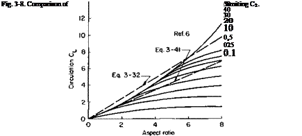
vortex system a limiting value is obtained for the lift of a finite wing due to circulation. Thus any device that attempts to increase the lift by increasing the circulation of a finite wing can never produce a lift coefficient greater than that given by (3-32). A comparison of (3-32) with experimental data obtained with jet-flapped wings [6] is presented in Fig. 3-8. As predicted, the experimental CL increases approximately linearly with the aspect ratio.
An implicit relationship can be derived between the induced drag of the wing and its lift. According to the approximation of Fig. 3-7, the drag of the wing is given by
D = pw cos ctjT.
In a manner similar to that used for CL the induced drag coefficient becomes
 (3-33)
Recall that TJlbV = w/V. If w is assumed to be small in comparison with V, then (3-31) and (3-33)-become
or
![]() C°M ttAR
C°M ttAR
The sub 0 refers to the fact that these relationships are all according to conventional wing theory.
This is the usual result obtained from ordinary lifting line theory that provides us with an insight into the analysis of (3-33). Using (3-31) and (3-33) and dividing CD. by Cl/nAR, we obtain
 (3-35)
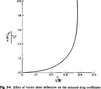
This relationship is presented graphically in Fig. 3-9 as a function of CJnAR. The departure of (71AR CD)jC from unity is a measure of the error involved in conventional wing theory. Observe that for CJnAR = 0.384, corresponding to the maximum value that this parameter can ever attain, the induced drag coefficient is nearly double that predictable on the basis of (3-34).
In order to gain an appreciation of these higher-order effects on the lift curve of a wing, consider the hypothetical case of an elliptic wing that generates circulation by angle of attack only. Further, unlike exact two – dimensional airfoil theory, which predicts that C, will vary as the sin a, some means is present to ensure that C, will vary linearly with a. Thus any departure from ordinary wing theory will be the result of accounting for the deflection of the vortex sheet and not the use of different two-dimensional characteristics.
In terms of the section slope of the lift curve, the force F in Fig. 3-7 would be given by
F = p{V2 – w2)ca0{<x – a,).
By resolving this in the lift direction, we have
L = p(V2— w2)ca0(a — a,) cos at
or
![]()
 (3-36)
 |
But CL was given before by (3-31) as a function of Г0/2bV. In view of the implicit relationship between CL, Г0, AR, and a, these results are presented
graphically in Fig. 3-10. Here, again, the value of CL is given as a proportion of the value that would have been calculated by using conventional wing theory. The relationship between CL, AR, and a, according to usual practice, can be readily obtained from (3-36) and (3-31) by assuming T0/2bV « 1 so that
, = a0«
![]()
Lo 1 + aJnPR.
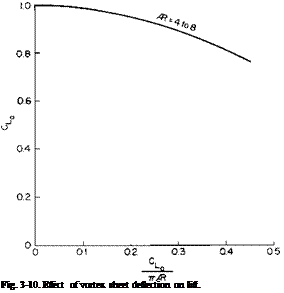 |
From this figure it can be seen that there is no dependence of the ratio CJCLo on the aspect ratio for the range considered when plotted versus CLo/7tAR. With regard to the errors that might be incurred if we applied ordinary wing theory to high-lift wings, consider a wing with an aspect ratio of 6. Suppose that, on the basis of two-dimensional airfoil data and conventional wing theory, the wing was predicted to develop a CLo of 4 [from (3-32) the maximum it could develop would be 7.25]. From Fig. 3-10, for CLJnAR of 0.212, a value of CJCIo of 0.936 is read. Thus the lift coefficient the wing would actually produce under the conditions in which it was expected to produce 4 would be only 3.75.
Although this development was limited to an elliptic Г-distribution, it might be expected that the results presented in Figs. 3-9 and 3-10 and Eq. (3-32) would hold equally well for other wings. The distributions of most wings approximate the elliptic. The results of conventional wing theory for elliptic wings, as expressed by (3-34) and (3-37) can be applied to most wings with small correction factors. Also, it should be kept in mind that the developments assume that the trailing vortex sheet is shed from the wing as a plane surface deflected downward at an angle determined by the velocity
induced at the start of the sheet. In view of the agreement between theory and experiment shown in Fig. 3-8, it would seem that the predictions of Figs. 3-9 and 3-10 are also valid.
Exact Solution of Elliptic Wing
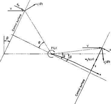
As stated earlier, it is possible to determine the exact forces on a wing with an elliptic Г-distribution. This is accomplished by applying the momentum theorem to control surfaces far ahead of and behind the wing. Consider
|
Fig. 3-11. Momentum through control surfaces ahead of and behind a wing section. |
Fig. 3-11 which shows a section of the wing with a circulation Г(у) about it. The control surfaces are taken normal to the ultimate direction of the trailing vortex sheet. If z is the direction along the control surfaces in the plane of the section, у is in the direction of the span and x is perpendicular to у and z, then from the momentum theorem
J*J* ^cos ^ v‘ s’n cos ^ + ^z’
JJ (Po – P) dy dz
в is the angle shown in the figure, vt is the velocity induced by Г, wz is the z-component induced by the trailing vortex sheet. The velocity vt contributes nothing to the change in the momentum flux in the x-direction. Because of the choice in the direction of the control surfaces, the vortex sheet contributes nothing to the momentum flux in the x direction; p0 is the static pressure that exists on the forward control surface, whereas p is the static pressure that exists on the after control surface. The integration is performed over the after control surface from z = — oo to oo and у equal to the width of the section.
The expression for Fz can be expanded to give
From the symmetry of the problem
w,(z) = wz(-z),
Ф) = Vi(-Z),
0(z) = – d(-z),
so that the second and third integrals vanish when evaluated over z from – со to oo. From the definition of circulation the first integral is obviously equal to Г(у). Hence
тг
![]() pV Г(у) cos P dy.
pV Г(у) cos P dy.
J-b/2
The pressure p can be determined by applying Bernoulli’s equation.
Po + ip[(F cos P + vt sin в)2 + (V sin P + v, cos 0)2]
= P + ip[(F cos p + vt sin в)2 + (V sin P — vt cos в — wz)2 + w2];
wz and wy are the velocity components induced by the trailing vortex sheet on the after control surface.
From the above the force F, becomes
In the limit, as z -► oo, i-> 0 so that the second integral vanishes. As stated previously, the first integral is equal to Г, whereas the last integral is seen
to be equal to the kinetic energy per unit length of the flow associated with the trailing vortex system. Thus
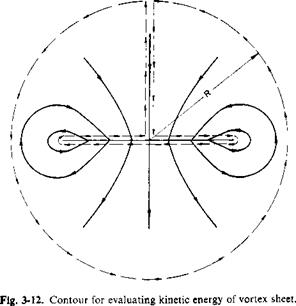
To evaluate the integral in the expression for Fx consider the flow in a plane transverse to the trailing vortex system, as shown in Fig. 3-12. In terms of a stream function, the kinetic energy (KE) per unit length, can be written
This can be rewritten as:
since
![]() /dwz dw
/dwz dw
dy dz
The surface integral in the expression for the kinetic energy can be transformed to a contour integral by Stoke’s theorem. Thus
KE = У ф (фчі) • dR.
The above can be evaluated as the limit of the integral around the dashed contour in Fig. 3-12 as R -» oo. In the limit the contribution to the integral around the outer circle of radius R can be shown to vanish. In addition, ф = 0 along the vertical path so that KE reduces to
ГЬ/2
KE = p іj/wy dy,
J-bl 2
where ф and wy are evaluated along the upper surface of the vortex sheet. Along this path ф = wzy, where wz is the downwash in the ultimate wake; wy is equal to one half the running strength of the vortex sheet. Thus for the elliptic distribution,
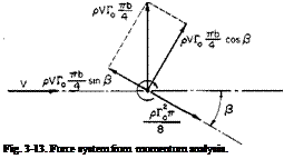
If the remainder of the expression for Fx and Fz is integrated from — bjl to b/2, the total Fx and Fz acting on the wing becomes
Fz = рУГ^ ~ cos P,
г т/г nb ■ а. рГол
– Fx = — рУГ0 — sin ^ H -—
These forces result in the force system shown in Fig. 3-13. Thus the lift and drag become
 |
D-^cosS.
Use of the fact that sin /5 = TJbV results finally in the following expressions for CL and CD.

 (3-39)
(3-40)
 |
The differences between the exact solution and the approximation already developed can be seen by comparing the above with (3-31) and (3-33). According to (3-39), the maximum value of CL is
(3-41)
 |
Equation (3-41) is lower than (3-32) and, as seen in Fig. 3-8, it agrees closely with experimental data for small aspect ratios but does not agree so
well as (3-32) for the higher aspect ratios. The reasons might be attributed to viscous effects, as mentioned before, or possibly to the fact that the vortex sheet is unstable and rolls up into two discrete vortices.
Linearized Lifting Line Theory
In the usual linearized lifting line theory the deflection of the trailing vortex sheet is neglected. It is assumed that the local angles of attack of each section of the wing are reduced by an induced angle of attack, a„ given by
 (3-42)
Thus the section C, is given by C, = a0(a – a,);
but C, is related to Г by Г = jcC, V so that
Again, using (3-28)
 (3-43)

The circulation distribution is now represented by a Fourier series in 0. Because of the symmetry, only sin пв terms are needed.

By selecting к values of 0O, knowing the corresponding values of a and c, we obtain к simultaneous equations for the unknowns Au A2, A3, Ak. The total lift of the wing can be obtained from


