Autorotation in Forward Flight
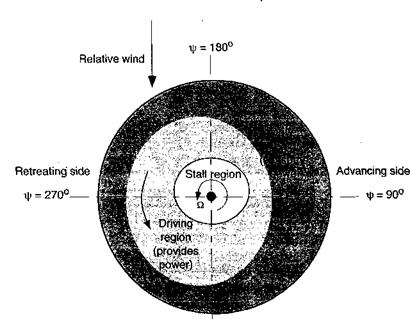
The autorotative energy balance in forward flight is basically the same as for vertical flight. However, because of the forward flight velocity there is a loss of axial symmetry in the induced velocity and angles of attack over the rotor disk. This tends to move the distribution of parts of the rotor disk that consume power and absorb power, as shown in Fig. 5.26. The stalled region may become biased toward the retreating side of the disk. However, the basic physics of the autorotational problem remains unchanged. Estimates of the autorotative rate of descent in forward flight can be made using the power equation given in terms of the momentum and blade element theories. While at low airspeeds autorotation takes place in the turbulent wake state, which is not strictly amenable to analysis by momentum theory without empirical correction, with some forward speed the flow state becomes much smoother. This means that the standard power equation can give results that are sufficiently accurate for engineering estimates of the rate of descent in autorotation as long as averaged flow properties are considered.
In an autorotation Cq = 0, so that to a first approximation (and neglecting the tail rotor) to the rate of descent and finding the speed to fly for minimum rate of descent we can use a rearrangement of the power equation (e. g., Eq. 5.53) to give
This equation applies down to descent angle and high rotor disk AoA, where the induced velocity through the rotor then needs to be modeled empirically – see also Section 12.8. The result for the rate of descent would normally be expressed in ft/min so that Vj = 60Xd&R.
|
яр = 0° Figure 5.26 Autorotative torque distribution over the rotor disk in forward flight. |
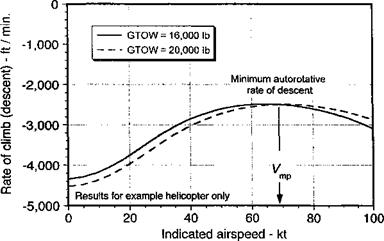
Representative results for the autorotative rate of descent in forward flight based on the use of the power equation are shown in Fig. 5.27. The shape of the curve mimics the power (or torque) required curve for steady level flight, as shown previously in Fig. 5.10 – see also Gessow & Myers (1947) and Wheatley (1932). Note the extremely high rates required at very low airspeeds, but for near Утр (airspeed for minimum power under normal flight conditions), the rate of descent is reduced to about half the value required in axial (vertical) flight. Therefore, should a problem arise that requires the pilot to put the aircraft
|
Figure 5.27 Estimates of rate of descent in autorotation for example helicopter. |
It is likely that an actual autorotation will have to be performed away from the vicinity of an airport, and maximizing the time to complete the descent is essential for choosing a suitable landing area. Although the autorotative rate of descent is always high, the actual autorotative entry is a relatively safe and benign maneuver from the pilot’s perspective when sufficient altitude is available. The final stages of the autorotation happen more quickly, however, and require great piloting skill. At about 50 ft (17 m) from the ground, the pilot must begin to decelerate the helicopter. This is done by slowly pulling up on the collective pitch (increasing blade pitch angles and so initially increasing rotor thrust), while simultaneously pulling back on the cyclic to flare the helicopter, increase the disk AoA, and reduce forward speed. As the collective pitch is increased, the unpowered rotor rpm will reduce quickly and so the pilot must ensure that the collective is brought in progressively and at a rate that still allows the rpm of the unpowered rotor to stay within acceptable values to produce thrust and prevent blade stall. Increasing the disk AoA to give the helicopter a steep nose-high attitude in the flare will tend to maintain rotor rpm as the component of forward velocity normal to the disk plane now helps to maintain the rotor in autorotation. The probability of success or otherwise of the resulting attempt at autorotation depends on many factors, including the exact pitch and roll angle of the helicopter when engine or mechanical failure occurred, overall pilot workload and the need to maneuver the helicopter as much as possible “into wind” to minimize ground speed at touchdown, and the need to find a suitable landing site free of obstructions.
 |
|
It will be apparent that the time constant r in Eq. 5.89 will also govern the decay of the rotor rpm as the pilot raises the collective pitch and uses cyclic pitch to flare the helicopter. Because a reduction in rotor rpm also decreases rotor thrust, the consideration of rotor stall margins are also important here. Because rotor thrust is essentially proportional to £22 the lowest acceptable rotor rpm (£2staii) can be determined by using
where the A(Cr /cr)stall is the stall margin in terms of blade loading coefficient. Even though the stall margin on most helicopters at high gross weights is relatively modest, the allowable decay in rotor rpm during the flare maneuver is fairly generous while still avoiding stall. However, even without blade stall as an issue, the rotor rpm must also be maintained to avoid excessive blade flapping from flapwise blade inertia loads, especially as the helicopter touches down. There have been several serious accidents during the autorotative maneuver as a result of the pilot allowing low rotor rpm and so producing excessive blade flapping, which can cause the blades to strike the airframe. The overall objective for the pilot is to cushion the rate of descent such that the helicopter touches down with a rate of descent of less than about 10 ft s-1 (~ 3 ms-1) with minimal forward speed.


